|
|
| 1번째 줄: |
1번째 줄: |
| | 광통신용 계측기 | | 광통신용 계측기 |
| | <ol> | | <ol> |
| − | <li>링크 | + | <li> [[전자부품]] |
| | + | <ol> |
| | + | <li>계측기 |
| | + | <ol> |
| | + | <li> [[OmniBER]] 광통신용 계측기 - 이 페이지 |
| | <ol> | | <ol> |
| − | <li> [[전자부품]] | + | <li> [[OmniBER 725, Optical Interface]] |
| | + | <li> [[OmniBER 725, Binary Interface]] |
| | + | <li> [[OmniBER 725, Multirate Analyzer]] |
| | + | <li> [[OmniBER 725, Clock]] |
| | + | <li> [[OmniBER 725, Aux Clock]] |
| | + | <li> [[OmniBER 725, Jitter]] |
| | + | <li> [[OmniBER 725, Controller]] |
| | + | <li> [[OmniBER 725, Power]] |
| | + | <li> [[OmniBER 725, Front Panel]] |
| | + | <li> [[OmniBER 725, Backplane]] |
| | + | <li> [[cross flow팬]] |
| | + | <li> [[펜탁스 PT-A4301]] 프린터 |
| | + | </ol> |
| | + | </ol> |
| | </ol> | | </ol> |
| | <li>HP J1409A OmniBER 725, Communications Performance Analyzer | | <li>HP J1409A OmniBER 725, Communications Performance Analyzer |
| 11번째 줄: |
28번째 줄: |
| | <li>구입이력 | | <li>구입이력 |
| | <ol> | | <ol> |
| − | <li>18/12/16 - 7p, 관세포함 151,433원 | + | <li>18/12/16 - 7p |
| | <ol> | | <ol> |
| | <li>J1409A - BER and jitter capability (반면 J1408A은 BER 측정만) | | <li>J1409A - BER and jitter capability (반면 J1408A은 BER 측정만) |
| 33번째 줄: |
50번째 줄: |
| | <li>외관 | | <li>외관 |
| | <gallery> | | <gallery> |
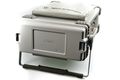
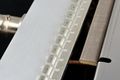
| − | image:j1409a00_001.jpg | + | image:j1409a00_001.jpg | 전면에 뚜껑이 있다. |
| − | image:j1409a00_002.jpg | + | image:j1409a00_002.jpg | 전면 뚜껑을 열면 |
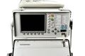
| − | image:j1409a00_004.jpg | + | image:j1409a00_004.jpg | Agilent OmniBER 725 |
| − | image:j1409a00_005.jpg | + | image:j1409a00_005.jpg | 뒷면에는 냉각 팬만 보인다. |
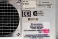
| − | image:j1409a00_006.jpg | 2001년 3월 영국에서 제조 | + | image:j1409a00_006.jpg | Product No. J1409A, 2001년 3월 영국에서 제조 |
| | </gallery> | | </gallery> |
| − | <li>슬롯 | + | <li>측면에 슬롯이 있다. |
| | <gallery> | | <gallery> |
| | image:j1409a00_007.jpg | | image:j1409a00_007.jpg |
| | + | image:j1409a00_009.jpg | 연결되지 않는 단자에, Inmet 3016A [[SMA 커넥터]] 50오옴 로드 8개가 꼽혀 있다. |
| | image:j1409a00_008.jpg | | image:j1409a00_008.jpg |
| − | image:j1409a00_009.jpg | + | image:j1409a00_011.jpg | [[BNC 커넥터]] 75오옴이라고 적혀 있지만, 구조는 50오옴이다. |
| | image:j1409a00_010.jpg | FC/PC optical connector adapter | | image:j1409a00_010.jpg | FC/PC optical connector adapter |
| − | image:j1409a00_011.jpg | 커넥터는 50오옴인데...
| |
| | </gallery> | | </gallery> |
| | <li>분해, 내부 커넥터 | | <li>분해, 내부 커넥터 |
| 55번째 줄: |
72번째 줄: |
| | image:j1409a00_014_001.jpg | | image:j1409a00_014_001.jpg |
| | </gallery> | | </gallery> |
| − | <li>전면 패널(디스플레이, 조작부)
| |
| − | <ol>
| |
| − | <li>분해전
| |
| − | <gallery>
| |
| − | image:j1409a00_044.jpg
| |
| − | image:j1409a00_047_008.jpg
| |
| − | </gallery>
| |
| − | <li>LED 표시부, 외부 인터페이스부
| |
| − | <gallery>
| |
| − | image:j1409a00_048.jpg
| |
| − | image:j1409a00_047_007.jpg
| |
| − | image:j1409a00_047_002.jpg | 모듈라 잭
| |
| − | image:j1409a00_047_001.jpg
| |
| − | image:j1409a00_047_003.jpg | LED 리드 고정방법
| |
| − | image:j1409a00_047_004.jpg | 테스트 핀
| |
| − | image:j1409a00_047_005.jpg | 페라이트 비드
| |
| − | image:j1409a00_047_006.jpg | CMF, Pulse PE-62911
| |
| − | </gallery>
| |
| − | <li>LCD 화면 제어기
| |
| − | <ol>
| |
| − | <li>분해전<gallery>
| |
| − | image:j1409a00_045.jpg
| |
| − | </gallery>
| |
| − | <li>앞면<gallery>
| |
| − | image:j1409a00_047_009.jpg
| |
| − | image:j1409a00_045_001.jpg | J-lead PLCC(Plastic Leaded Chip Carrier) socket
| |
| − | image:j1409a00_046.jpg | LED 색
| |
| − | image:j1409a00_047.jpg | LED 색
| |
| − | </gallery>
| |
| − | <li>뒤면<gallery>
| |
| − | image:j1409a00_047_010.jpg
| |
| − | image:j1409a00_047_011.jpg
| |
| − | image:j1409a00_047_012.jpg
| |
| − | image:j1409a00_047_013.jpg
| |
| − | </gallery>
| |
| − | <li>LCD 부
| |
| − | <gallery>
| |
| − | image:j1409a00_047_019.jpg
| |
| − | image:j1409a00_047_020.jpg
| |
| − | image:j1409a00_047_021.jpg
| |
| − | </gallery>
| |
| − | <li>LCD CCFL 백라이트 전원부
| |
| − | <gallery>
| |
| − | image:j1409a00_047_014.jpg
| |
| − | image:j1409a00_047_015.jpg
| |
| − | image:j1409a00_047_016.jpg
| |
| − | image:j1409a00_047_017.jpg
| |
| − | image:j1409a00_047_018.jpg
| |
| − | </gallery>
| |
| − | <li>버튼
| |
| − | <gallery>
| |
| − | image:j1409a00_047_022.jpg
| |
| − | image:j1409a00_047_023.jpg
| |
| − | image:j1409a00_047_024.jpg
| |
| − | image:j1409a00_047_025.jpg
| |
| − | image:j1409a00_047_026.jpg
| |
| − | </gallery>
| |
| − | </ol>
| |
| − | <li>backplane
| |
| − | <ol>
| |
| − | <li>전체
| |
| − | <gallery>
| |
| − | image:j1409a00_016.jpg
| |
| − | </gallery>
| |
| − | <li>팬 부착
| |
| − | <gallery>
| |
| − | image:j1409a00_017.jpg | 팬
| |
| − | </gallery>
| |
| − | <li>전원 연결
| |
| − | <gallery>
| |
| − | image:j1409a00_049.jpg
| |
| − | image:j1409a00_051.jpg
| |
| − | image:j1409a00_052.jpg
| |
| − | image:j1409a00_053.jpg
| |
| − | image:j1409a00_053_001.jpg
| |
| − | image:j1409a00_050.jpg
| |
| − | image:j1409a00_050_001.jpg
| |
| − | </gallery>
| |
| − | <li>바이메탈 과열 방지기
| |
| − | <gallery>
| |
| − | image:j1409a00_054.jpg
| |
| − | image:j1409a00_055.jpg
| |
| − | image:j1409a00_056.jpg
| |
| − | image:j1409a00_057.jpg
| |
| − | image:j1409a00_058.jpg
| |
| − | image:j1409a00_059.jpg
| |
| − | </gallery>
| |
| − | </ol>
| |
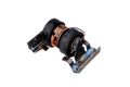
| − | <li>fan - tangential fan, (회전축 중심으로 공기가 들어가는 원심력 팬 centrifugal fan은 아니다.)
| |
| − | <ol>
| |
| − | <li>외관
| |
| − | <gallery>
| |
| − | image:j1409a00_036.jpg
| |
| − | image:j1409a00_037.jpg
| |
| − | image:j1409a00_038.jpg
| |
| − | </gallery>
| |
| − | <li>팬 분해
| |
| − | <gallery>
| |
| − | image:j1409a00_038_001.jpg | 고무 댐핑
| |
| − | image:j1409a00_038_002.jpg
| |
| − | image:j1409a00_038_003.jpg
| |
| − | image:j1409a00_038_004.jpg
| |
| − | image:j1409a00_038_012.jpg
| |
| − | image:j1409a00_038_013.jpg
| |
| − | image:j1409a00_038_014.jpg
| |
| − | image:j1409a00_038_005.jpg
| |
| − | image:j1409a00_038_015.jpg | 합성사진
| |
| − | </gallery>
| |
| − | <li>모터 분해
| |
| − | <gallery>
| |
| − | image:j1409a00_038_006.jpg | 풀칠하고 압입
| |
| − | image:j1409a00_038_007.jpg
| |
| − | image:j1409a00_038_008.jpg | BA6406 IC(Two-Phase Half-Wave Pre Driver), 2SD1760(NPN, 60V 3A) 모두 Rhom
| |
| − | image:j1409a00_038_009.jpg | 홀소자
| |
| − | image:j1409a00_038_010.jpg
| |
| − | image:j1409a00_038_011.jpg
| |
| − | </gallery>
| |
| − | <li>모터 코어 분해
| |
| − | <gallery>
| |
| − | image:j1409a00_038_016.jpg
| |
| − | image:j1409a00_038_017.jpg
| |
| − | image:j1409a00_038_018.jpg
| |
| − | image:j1409a00_038_019.jpg
| |
| − | image:j1409a00_038_020.jpg
| |
| − | image:j1409a00_038_021.jpg
| |
| − | </gallery>
| |
| − | </ol>
| |
| − | <li>lid printer
| |
| − | <ol>
| |
| − | <li>표시
| |
| − | <gallery>
| |
| − | image:j1409a00_003.jpg | 써멀종이 프린터
| |
| − | </gallery>
| |
| − | <li>외관
| |
| − | <gallery>
| |
| − | image:j1409a00_039.jpg
| |
| − | image:j1409a00_040.jpg
| |
| − | image:j1409a00_041.jpg
| |
| − | image:j1409a00_042.jpg
| |
| − | image:j1409a00_043.jpg
| |
| − | </gallery>
| |
| − | <li>케이블
| |
| − | <ol>
| |
| − | <li>모듈라 잭
| |
| − | <gallery>
| |
| − | image:j1409a00_039_001.jpg | 8핀 RJ45보다 더 넓다
| |
| − | image:j1409a00_039_002.jpg
| |
| − | image:j1409a00_039_003.jpg | 1.27mm 피치(0.05인치, 표준 ribbon cable) 케이블
| |
| − | image:j1409a00_039_004.jpg
| |
| − | image:j1409a00_039_005.jpg | RJ45와 비교
| |
| − | image:j1409a00_039_006.jpg
| |
| − | image:j1409a00_039_007.jpg | RJ45
| |
| − | </gallery>
| |
| − | <li>전원, 프린터용 직렬통신 케이블
| |
| − | <gallery>
| |
| − | image:j1409a00_042_001.jpg | 4개를 한꺼번에 연결할 수도 있다.
| |
| − | image:j1409a00_042_002.jpg
| |
| − | image:j1409a00_042_003.jpg | 선 2개 접속
| |
| − | image:j1409a00_042_004.jpg | 실드 방법
| |
| − | </gallery>
| |
| − | </ol>
| |
| − | <li>분해
| |
| − | <gallery>
| |
| − | image:j1409a00_076.jpg
| |
| − | image:j1409a00_077.jpg
| |
| − | </gallery>
| |
| − | <li>indicator LED 3개 및 종이 감지 센서
| |
| − | <gallery>
| |
| − | image:j1409a00_078.jpg
| |
| − | image:j1409a00_079.jpg
| |
| − | image:j1409a00_080.jpg
| |
| − | </gallery>
| |
| − | <li>종이 이송
| |
| − | <gallery>
| |
| − | image:j1409a00_074.jpg
| |
| − | image:j1409a00_075.jpg | DC stepper motor 인듯.
| |
| − | </gallery>
| |
| − | <li>TPH
| |
| − | <gallery>
| |
| − | image:j1409a00_081.jpg
| |
| − | image:j1409a00_082.jpg | KPT-219-12MWW4-AKG R=2740 06-00020 (Kyocera Print Head?)
| |
| − | image:j1409a00_083.jpg
| |
| − | image:j1409a00_084.jpg
| |
| − | image:j1409a00_085.jpg
| |
| − | image:j1409a00_086.jpg
| |
| − | image:j1409a00_087.jpg
| |
| − | image:j1409a00_088.jpg
| |
| − | image:j1409a00_089.jpg
| |
| − | image:j1409a00_090.jpg
| |
| − | </gallery>
| |
| − | <li>PCB 앞, 뒤
| |
| − | <ol>
| |
| − | <li>보드 및 IC
| |
| − | <gallery>
| |
| − | image:j1409a00_091.jpg
| |
| − | image:j1409a00_092.jpg
| |
| − | image:j1409a00_092_001.jpg | J-lead
| |
| − | image:j1409a00_093.jpg
| |
| − | image:j1409a00_094.jpg
| |
| − | </gallery>
| |
| − | <li>X-tal
| |
| − | <gallery>
| |
| − | image:j1409a00_092_002.jpg
| |
| − | image:j1409a00_092_003.jpg
| |
| − | </gallery>
| |
| − | <li>3단자 어레이 필터, Murata NFA 221
| |
| − | <gallery>
| |
| − | image:j1409a00_095.jpg
| |
| − | image:j1409a00_096.jpg
| |
| − | </gallery>
| |
| − | <li>3단자 필터 - C로만 구성
| |
| − | <gallery>
| |
| − | image:j1409a00_097.jpg
| |
| − | image:j1409a00_099.jpg
| |
| − | </gallery>
| |
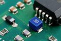
| − | <li>DIP 스위치
| |
| − | <gallery>
| |
| − | image:j1409a00_098.jpg
| |
| − | image:j1409a00_098_001.jpg
| |
| − | image:j1409a00_098_002.jpg
| |
| − | </gallery>
| |
| − | <li>1.1오옴, 검정 저항체를 L 트리밍하였다.
| |
| − | <gallery>
| |
| − | image:j1409a00_100.jpg
| |
| − | image:j1409a00_100_001.jpg
| |
| − | image:j1409a00_100_002.jpg
| |
| − | </gallery>
| |
| − | <li>점퍼, 퓨즈 설치도 고려하여
| |
| − | <gallery>
| |
| − | image:j1409a00_100_003.jpg
| |
| − | image:j1409a00_100_004.jpg
| |
| − | </gallery>
| |
| − | <li>점퍼, L이라고 기록되어 있지만
| |
| − | <gallery>
| |
| − | image:j1409a00_100_005.jpg
| |
| − | image:j1409a00_100_006.jpg
| |
| − | </gallery>
| |
| − | </ol>
| |
| − | </ol>
| |
| | <li>보드 공통 | | <li>보드 공통 |
| | <ol> | | <ol> |
| 409번째 줄: |
187번째 줄: |
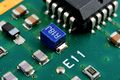
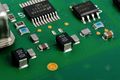
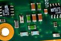
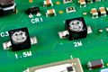
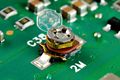
| | <li>정밀 OP용 정밀 저항 - Optical Interface에서 | | <li>정밀 OP용 정밀 저항 - Optical Interface에서 |
| | <ol> | | <ol> |
| − | <li><gallery> | + | <li>가드링(Guard Ring)이 존재하는 곳이다. |
| | + | <gallery> |
| | image:j1409a00_025_015.jpg | | image:j1409a00_025_015.jpg |
| | image:j1409a00_025_016.jpg | | image:j1409a00_025_016.jpg |
| | image:j1409a00_025_017.jpg | | image:j1409a00_025_017.jpg |
| | </gallery> | | </gallery> |
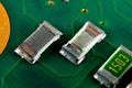
| − | <li><gallery> | + | <li>두 개 표면 벗기면(모두 에폭시 코팅되어 있음) |
| − | image:j1409a00_025_017_001.jpg | 두 개 표면 벗기면(모두 에폭시 코팅되어 있음) | + | <gallery> |
| | + | image:j1409a00_025_017_001.jpg |
| | + | image:j1409a00_025_017_005.jpg | 트리밍 방법 1,2 |
| | + | image:j1409a00_025_017_006.jpg | 트리밍 방법 1,2 |
| | </gallery> | | </gallery> |
| − | <li><gallery> | + | <li>트리밍 방법 1 |
| | + | <gallery> |
| | image:j1409a00_025_017_002.jpg | | image:j1409a00_025_017_002.jpg |
| | </gallery> | | </gallery> |
| − | <li><gallery> | + | <li>트리밍 방법 2 |
| | + | <gallery> |
| | image:j1409a00_025_017_003.jpg | | image:j1409a00_025_017_003.jpg |
| | image:j1409a00_025_017_004.jpg | | image:j1409a00_025_017_004.jpg |
| − | image:j1409a00_025_017_005.jpg
| |
| − | image:j1409a00_025_017_006.jpg
| |
| | image:j1409a00_025_017_007.jpg | | image:j1409a00_025_017_007.jpg |
| | </gallery> | | </gallery> |
| | + | </ol> |
| | </ol> | | </ol> |
| | <li>75오옴(?) 케이블 - Multirate Analyzer 보드에서 | | <li>75오옴(?) 케이블 - Multirate Analyzer 보드에서 |
| 460번째 줄: |
243번째 줄: |
| | image:j1409a00_035_019.jpg | | image:j1409a00_035_019.jpg |
| | </gallery> | | </gallery> |
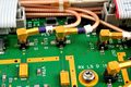
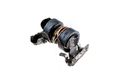
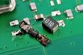
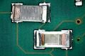
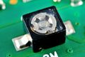
| − | <li>레귤레이터 IC 방열 - 클럭 보드에서 | + | <li>[[리니어 레귤레이터]] 방열 - 클럭 보드에서 |
| | <gallery> | | <gallery> |
| | image:j1409a00_031_021.jpg | | image:j1409a00_031_021.jpg |
| 469번째 줄: |
252번째 줄: |
| | image:j1409a00_031_021_005.jpg | | image:j1409a00_031_021_005.jpg |
| | </gallery> | | </gallery> |
| − | </ol>
| |
| − | <li>Optical Interface
| |
| − | <ol>
| |
| − | <li>외관
| |
| − | <gallery>
| |
| − | image:j1409a00_021.jpg
| |
| − | image:j1409a00_022.jpg
| |
| − | image:j1409a00_023.jpg
| |
| − | image:j1409a00_024.jpg
| |
| − | image:j1409a00_025.jpg
| |
| − | </gallery>
| |
| − | <li>관련 부품
| |
| − | <ol>
| |
| − | <li>기타
| |
| − | <gallery>
| |
| − | image:j1409a00_025_003.jpg
| |
| − | image:j1409a00_025_004.jpg
| |
| − | image:j1409a00_025_007.jpg
| |
| − | image:j1409a00_031_014_001.jpg | micro-X package = 4 lead plastic micro-p package
| |
| − | image:j1409a00_025_008.jpg
| |
| − | image:j1409a00_025_009.jpg
| |
| − | image:j1409a00_025_014.jpg | 수리
| |
| − | image:j1409a00_025_018.jpg
| |
| − | image:j1409a00_025_019.jpg
| |
| − | image:j1409a00_024_017.jpg | Osc
| |
| − | </gallery>
| |
| − | <li>필터-1
| |
| − | <gallery>
| |
| − | image:j1409a00_025_003.jpg
| |
| − | image:j1409a00_025_003_001.jpg
| |
| − | image:j1409a00_025_003_002.jpg
| |
| − | image:j1409a00_025_003_003.jpg
| |
| − | image:j1409a00_025_003_004.jpg
| |
| − | </gallery>
| |
| − | <li>필터-2
| |
| − | <gallery>
| |
| − | image:j1409a00_025_006.jpg
| |
| − | image:j1409a00_025_005.jpg
| |
| − | image:j1409a00_025_005_001.jpg
| |
| − | image:j1409a00_025_005_002.jpg
| |
| − | image:j1409a00_025_005_003.png
| |
| − | </gallery>
| |
| − | <li>어떤 IC 방열
| |
| − | <gallery>
| |
| − | image:j1409a00_025_013.jpg
| |
| − | image:j1409a00_025_013_001.jpg
| |
| − | image:j1409a00_025_013_002.jpg | 접착력이 크다.
| |
| − | </gallery>
| |
| − | <li>RF 코일
| |
| − | <gallery>
| |
| − | image:j1409a00_025_020.jpg
| |
| − | image:j1409a00_025_021.jpg | 2.0x1.4mm, L 홈 페이지 참조 1.3nH 0.47nH로 추정
| |
| − | </gallery>
| |
| − | <li>delay line = meander microstrip delay line(MMDL)
| |
| − | <ol>
| |
| − | <li>규격서
| |
| − | <li>사진
| |
| − | <gallery>
| |
| − | image:j1409a00_024_001.jpg
| |
| − | image:j1409a00_024_002.jpg
| |
| − | image:j1409a00_024_003.jpg
| |
| − | image:j1409a00_024_004.jpg
| |
| − | image:j1409a00_024_005.jpg
| |
| − | image:j1409a00_024_016.jpg
| |
| − | </gallery>
| |
| − | <li>측정
| |
| − | <ol>
| |
| − | <li> 왕복 8.5n (50매칭에서 일찍 벗어나므로 약간 짧게 측정되는 듯
| |
| − | <gallery>
| |
| − | image:j1409a00_024_006.png
| |
| − | </gallery>
| |
| − | <li>네트워크 분석기로 delay 측정
| |
| − | <gallery>
| |
| − | image:j1409a00_024_007.jpg
| |
| − | image:j1409a00_024_008.jpg
| |
| − | image:j1409a00_024_009.jpg
| |
| − | image:j1409a00_024_010.png | 통과이득
| |
| − | image:j1409a00_024_011.png | 위상
| |
| − | image:j1409a00_024_012.png | 지연 4.40nsec
| |
| − | </gallery>
| |
| − | <li>스트립라인 치수 측정
| |
| − | <gallery>
| |
| − | image:j1409a00_024_013.jpg
| |
| − | image:j1409a00_024_014.jpg
| |
| − | image:j1409a00_024_015.png
| |
| − | </gallery>
| |
| − | <li>5nsec 제품
| |
| − | <ol>
| |
| − | <li>1 layer = 폭 3.7mm 37개, 길이 11mm 2개, 총 길이 159mm
| |
| − | <li>3 layer = 159x3 = 477mm
| |
| − | <li>기타 도선이 +9mm 라면 총 486mm가 된다.
| |
| − | <li>알루미나 속도비 0.324
| |
| − | <li>0.324 x 광속(300) x 5nsec = 486mm
| |
| − | </ol>
| |
| − | </ol>
| |
| − | </ol>
| |
| − | </ol>
| |
| − | <li>광 커넥터(FC connector에서 FC/PC)를 받아들이는 소켓
| |
| − | <ol>
| |
| − | <li>외관
| |
| − | <gallery>
| |
| − | image:j1409a00_025_028.jpg
| |
| − | image:j1409a00_025_029.jpg
| |
| − | image:j1409a00_025_030.jpg
| |
| − | image:j1409a00_025_031.jpg
| |
| − | </gallery>
| |
| − | <li>접촉면
| |
| − | <gallery>
| |
| − | image:j1409a00_025_030_001.jpg
| |
| − | image:j1409a00_025_030_002.jpg
| |
| − | image:j1409a00_025_030_003.jpg | 광섬유 코어직경 약 63um
| |
| − | </gallery>
| |
| − | <li>여기와 연결된 오렌지색 광섬유
| |
| − | <gallery>
| |
| − | image:j1409a00_025_043_001.jpg
| |
| − | image:j1409a00_025_043_002.jpg | 코어 직경 약 60um(정확히 62.5um)
| |
| − | image:j1409a00_025_043_003.jpg
| |
| − | </gallery>
| |
| − | </ol>
| |
| − | <li>Rx/Tx 모듈
| |
| − | <gallery>
| |
| − | image:j1409a00_025_026.jpg
| |
| − | image:j1409a00_025_027.jpg
| |
| − | </gallery>
| |
| − | <li>Fiber Optic Receive Module
| |
| − | <ol>
| |
| − | <li>내부
| |
| − | <gallery>
| |
| − | image:j1409a00_025_032.jpg
| |
| − | image:j1409a00_025_033.jpg
| |
| − | image:j1409a00_025_037.jpg
| |
| − | image:j1409a00_025_038.jpg
| |
| − | image:j1409a00_025_039.jpg
| |
| − | image:j1409a00_025_040.jpg
| |
| − | </gallery>
| |
| − | <li>X 패키지
| |
| − | <gallery>
| |
| − | image:j1409a00_025_034.jpg
| |
| − | image:j1409a00_025_035.jpg
| |
| − | image:j1409a00_025_036.jpg
| |
| − | </gallery>
| |
| − | <li>포토다이오드 모듈
| |
| − | <gallery>
| |
| − | image:j1409a00_025_041.jpg
| |
| − | image:j1409a00_025_042.jpg
| |
| − | </gallery>
| |
| − | <li>포토다이오드
| |
| − | <gallery>
| |
| − | image:j1409a00_025_043.jpg
| |
| − | image:j1409a00_025_044.jpg
| |
| − | image:j1409a00_025_045.jpg
| |
| − | image:j1409a00_025_046.jpg
| |
| − | image:j1409a00_025_047.jpg
| |
| − | image:j1409a00_025_048.jpg
| |
| − | image:j1409a00_025_049.jpg
| |
| − | </gallery>
| |
| − | <li>모듈
| |
| − | <gallery>
| |
| − | image:j1409a00_025_050.jpg
| |
| − | image:j1409a00_025_051.jpg
| |
| − | image:j1409a00_025_052.jpg
| |
| − | image:j1409a00_025_053.jpg
| |
| − | image:j1409a00_025_054.jpg
| |
| − | image:j1409a00_025_055.jpg
| |
| − | image:j1409a00_025_056.jpg
| |
| − | image:j1409a00_025_057.jpg
| |
| − | image:j1409a00_025_058.jpg
| |
| − | image:j1409a00_025_059.jpg
| |
| − | image:j1409a00_025_060.jpg
| |
| − | image:j1409a00_025_061.jpg
| |
| − | image:j1409a00_025_062.jpg
| |
| − | image:j1409a00_025_063.jpg
| |
| − | image:j1409a00_025_064.jpg
| |
| − | image:j1409a00_025_065.jpg
| |
| − | image:j1409a00_025_066.jpg
| |
| − | image:j1409a00_025_067.jpg
| |
| − | </gallery>
| |
| − | <li>아날로그 IC
| |
| − | <gallery>
| |
| − | image:j1409a00_025_068.jpg
| |
| − | image:j1409a00_025_069.jpg
| |
| − | image:j1409a00_025_070.jpg
| |
| − | image:j1409a00_025_071.jpg
| |
| − | image:j1409a00_025_072.jpg
| |
| − | image:j1409a00_025_073.jpg
| |
| − | </gallery>
| |
| − | </ol>
| |
| − | <li>Fiber Optic Transmitter Module
| |
| − | <ol>
| |
| − | <li>설명
| |
| − | <ol>
| |
| − | <li>EEL; Edge-Emitting Laser(Wide divergent output; 여러 모드가 있어 옆으로 많이 퍼진다.) 과 VCSEL (빅셀은 빛이 single-longitudinal-mode이므로 광섬유 통신에 매우 유리하다. 출력이 약하다.)
| |
| − | <li> - 9p
| |
| − | <ol>
| |
| − | <li>1.5mm D2500-Type Digital Isolated DFB Laser Module, 2.488Gbits/s,
| |
| − | <li>1mW, 170km 전송가능, Spectral Width -3dB 0.2nm -20dB 0.8nm
| |
| − | </ol>
| |
| − | </ol>
| |
| − | <li>외관 (single-mode fiber with an 8um core and 125um cladding)
| |
| − | <gallery>
| |
| − | image:j1409a00_025_091.jpg
| |
| − | image:j1409a00_025_092.jpg
| |
| − | image:j1409a00_025_093.jpg | R93은 온도용 PID에 사용되는 듯.
| |
| − | image:j1409a00_025_094.jpg
| |
| − | image:j1409a00_025_095.jpg
| |
| − | image:j1409a00_025_096.jpg
| |
| − | image:j1409a00_025_098.jpg
| |
| − | image:j1409a00_025_099.jpg
| |
| − | </gallery>
| |
| − | <li>LD용 앰프
| |
| − | <gallery>
| |
| − | image:j1409a00_025_097.jpg
| |
| − | image:j1409a00_025_097_001.jpg
| |
| − | image:j1409a00_025_097_002.jpg
| |
| − | image:j1409a00_025_097_003.jpg
| |
| − | image:j1409a00_025_097_004.jpg
| |
| − | </gallery>
| |
| − | <li>LD 모듈 (=distributed feedback laser;DFB)
| |
| − | <gallery>
| |
| − | image:j1409a00_025_100.jpg | MJE200(npn) MJE210(pnp) 5A
| |
| − | image:j1409a00_025_101.jpg
| |
| − | image:j1409a00_025_102.jpg
| |
| − | image:j1409a00_025_103.jpg
| |
| − | image:j1409a00_025_104.jpg | 14-pin butterfly package
| |
| − | image:j1409a00_025_105.jpg
| |
| − | image:j1409a00_025_106.jpg | 레이저 용접
| |
| − | </gallery>
| |
| − | <li>리드 벗기기
| |
| − | <gallery>
| |
| − | image:j1409a00_025_107.jpg
| |
| − | image:j1409a00_025_108.jpg
| |
| − | image:j1409a00_025_109.jpg
| |
| − | image:j1409a00_025_110.jpg
| |
| − | image:j1409a00_025_111.jpg
| |
| − | image:j1409a00_025_112.jpg
| |
| − | image:j1409a00_025_113.jpg
| |
| − | image:j1409a00_025_114.jpg
| |
| − | image:j1409a00_025_115.jpg
| |
| − | image:j1409a00_025_119.jpg | optical isolator
| |
| − | </gallery>
| |
| − | <li>펠티어 peltier 소자 (thermoelectric cooler;TEC), bismuth telluride (Bi2Te3) 다결정. -40~+70도 환경에서 항상 25도씨 유지할 수 있다.
| |
| − | <gallery>
| |
| − | image:j1409a00_025_116.jpg
| |
| − | image:j1409a00_025_117.jpg
| |
| − | image:j1409a00_025_118.jpg
| |
| − | image:j1409a00_025_120.jpg
| |
| − | </gallery>
| |
| − | <li>확대
| |
| − | <gallery>
| |
| − | image:j1409a00_025_121.jpg
| |
| − | image:j1409a00_025_122.jpg
| |
| − | image:j1409a00_025_123.jpg
| |
| − | image:j1409a00_025_124.jpg
| |
| − | image:j1409a00_025_125.jpg
| |
| − | </gallery>
| |
| − | <li>맨 위에서 볼 때(뒤에 back-facet monitor PIN photodiode가 있다.)
| |
| − | <gallery>
| |
| − | image:j1409a00_025_126.jpg
| |
| − | image:j1409a00_025_127.jpg
| |
| − | image:j1409a00_025_128.jpg
| |
| − | </gallery>
| |
| − | <li>레이저 나오는 정면 부분 - 두 홈(passive waveguide) 사이에서 나온다.
| |
| − | <gallery>
| |
| − | image:j1409a00_025_129.jpg
| |
| − | image:j1409a00_025_130.jpg
| |
| − | image:j1409a00_025_131.jpg
| |
| − | </gallery>
| |
| − | <li>포토 다이오드 칩 뜯기
| |
| − | <gallery>
| |
| − | image:j1409a00_025_134.jpg
| |
| − | image:j1409a00_025_135.jpg
| |
| − | image:j1409a00_025_136.jpg
| |
| − | </gallery>
| |
| − | <li>레이저 다이오드 칩 뜨기
| |
| − | <gallery>
| |
| − | image:j1409a00_025_137.jpg
| |
| − | image:j1409a00_025_138.jpg
| |
| − | image:j1409a00_025_139.jpg
| |
| − | </gallery>
| |
| − | <li>기타
| |
| − | <gallery>
| |
| − | image:j1409a00_025_132.jpg | thermistor, 160uH L
| |
| − | image:j1409a00_025_133.jpg | 와이어 본딩
| |
| − | </gallery>
| |
| − | <li>본딩 위치
| |
| − | <gallery>
| |
| − | image:j1409a00_025_140.jpg
| |
| − | image:j1409a00_025_141.jpg
| |
| − | </gallery>
| |
| − | </ol>
| |
| − | <li>체배기, 앰프
| |
| − | <gallery>
| |
| − | image:j1409a00_025_074.jpg
| |
| − | image:j1409a00_025_075.jpg
| |
| − | image:j1409a00_025_076.jpg
| |
| − | image:j1409a00_025_077.jpg
| |
| − | image:j1409a00_025_078.jpg
| |
| − | image:j1409a00_025_079.jpg
| |
| − | image:j1409a00_025_080.jpg
| |
| − | image:j1409a00_025_081.jpg
| |
| − | image:j1409a00_025_082.jpg
| |
| − | image:j1409a00_025_083.jpg
| |
| − | image:j1409a00_025_084.jpg
| |
| − | </gallery>
| |
| − | <li>Bandpass Filter
| |
| − | <gallery>
| |
| − | image:j1409a00_025_085.jpg
| |
| − | image:j1409a00_025_086.jpg
| |
| − | image:j1409a00_025_087.jpg
| |
| − | image:j1409a00_025_088.jpg
| |
| − | image:j1409a00_025_089.png
| |
| − | image:j1409a00_025_090.png
| |
| − | </gallery>
| |
| − | </ol>
| |
| − | <li>Binary Interface
| |
| − | <ol>
| |
| − | <li>전체
| |
| − | <gallery>
| |
| − | image:j1409a00_026.jpg
| |
| − | </gallery>
| |
| − | <li>분해
| |
| − | <gallery>
| |
| − | image:j1409a00_026_001.jpg
| |
| − | image:j1409a00_026_002.jpg
| |
| − | image:j1409a00_026_004.jpg | 8개 ~18GHz termination이 마개로 사용
| |
| − | </gallery>
| |
| − | <li>접지 연결 포트 - attenuator 2dB가 연결되어 있음
| |
| − | <gallery>
| |
| − | image:j1409a00_026_003.jpg
| |
| − | </gallery>
| |
| − | <li>빈 PCB
| |
| − | <gallery>
| |
| − | image:j1409a00_026_005.jpg
| |
| − | image:j1409a00_026_006.jpg
| |
| − | image:j1409a00_026_007.jpg
| |
| − | </gallery>
| |
| − | <li>앞뒷면
| |
| − | <gallery>
| |
| − | image:j1409a00_026_008.jpg
| |
| − | image:j1409a00_026_009.jpg
| |
| − | image:j1409a00_026_013.jpg
| |
| − | image:j1409a00_026_015.jpg
| |
| − | </gallery>
| |
| − | <li>50오옴 점검용
| |
| − | <gallery>
| |
| − | image:j1409a00_026_015_001.jpg
| |
| − | image:j1409a00_026_015_002.jpg
| |
| − | image:j1409a00_026_015_003.jpg
| |
| − | image:j1409a00_026_015_004.jpg
| |
| − | image:j1409a00_026_015_005.png
| |
| − | image:j1409a00_026_015_006.png
| |
| − | </gallery>
| |
| − | <li>ferrite sleeve
| |
| − | <gallery>
| |
| − | image:j1409a00_026_010.jpg
| |
| − | image:j1409a00_026_011.jpg
| |
| − | image:j1409a00_026_011_001.jpg
| |
| − | </gallery>
| |
| − | <li>의미있는 부품 및 레이아웃
| |
| − | <gallery>
| |
| − | image:j1409a00_026_012.jpg | AMCC S3054
| |
| − | image:j1409a00_026_014.jpg | LUCENT 1605DXB
| |
| − | image:j1409a00_026_016.jpg | 밸런스 레이아웃
| |
| − | image:j1409a00_026_017.jpg | 어레이칩저항 배열
| |
| − | image:j1409a00_026_018.jpg | AMCC S3054 + 스위치
| |
| − | image:j1409a00_026_019.jpg | 밸런스 레이아웃 + 50오옴 칩저항
| |
| − | image:j1409a00_026_020.jpg | MAX3867 + 밸런스
| |
| − | image:j1409a00_026_029.jpg | MAX3867 + 밸런스
| |
| − | image:j1409a00_026_028.jpg | AMCC S3054 밸런스
| |
| − | image:j1409a00_026_030.jpg | LUCENT 1605DXB 밸런스
| |
| − | image:j1409a00_026_032.jpg | HEP33 밸런스 50오옴 칩저항
| |
| − | image:j1409a00_026_033.jpg | 접지 분리 위 점퍼
| |
| − | image:j1409a00_026_034.jpg | AMCC S3054 + 스위치 + 밸런스
| |
| − | </gallery>
| |
| − | <li>커플러 테스트 패턴
| |
| − | <gallery>
| |
| − | image:j1409a00_026_031.jpg
| |
| − | image:j1409a00_026_031_001.jpg | 4포트로 측정하는 법
| |
| − | image:j1409a00_026_031_002.jpg | 길이가 23mm. 1/4파장이 매칭이라면 1.8GHz 해당
| |
| − | image:j1409a00_026_031_003.png | 1.7GHz에서 -30dB 커플된다.
| |
| − | image:j1409a00_026_031_004.jpg
| |
| − | image:j1409a00_026_031_005.jpg | 2포트로 측정하는 법
| |
| − | </gallery>
| |
| − | <li>고주파 잡음 감쇄를 위해 작은 C를 덧붙임. - 손으로 납땜
| |
| − | <gallery>
| |
| − | image:j1409a00_026_021.jpg
| |
| − | image:j1409a00_026_022.jpg
| |
| − | image:j1409a00_026_023.jpg
| |
| − | image:j1409a00_026_024.jpg
| |
| − | image:j1409a00_026_025.jpg
| |
| − | image:j1409a00_026_026.jpg
| |
| − | image:j1409a00_026_027.jpg
| |
| − | </gallery>
| |
| − | </ol>
| |
| − | <li>Multirate Analyzer
| |
| − | <ol>
| |
| − | <li>전체
| |
| − | <gallery>
| |
| − | image:j1409a00_027.jpg
| |
| − | image:j1409a00_028.jpg
| |
| − | image:j1409a00_028_001.jpg
| |
| − | image:j1409a00_028_004.jpg
| |
| − | image:j1409a00_028_005.jpg
| |
| − | image:j1409a00_028_006.jpg
| |
| − | </gallery>
| |
| − | <li>관심 부품 및 레이아웃
| |
| − | <gallery>
| |
| − | image:j1409a00_028_014.jpg | 49.9오옴, 마킹 MLCC
| |
| − | image:j1409a00_028_015.jpg | 매칭 신호선
| |
| − | image:j1409a00_028_018.jpg | 49.9오옴
| |
| − | image:j1409a00_028_026.jpg | 마킹 MLCC
| |
| − | </gallery>
| |
| − | <li>케이블 길이 조사
| |
| − | <gallery>
| |
| − | image:j1409a00_028_009.jpg
| |
| − | image:j1409a00_028_010.jpg
| |
| − | image:j1409a00_028_011.jpg
| |
| − | image:j1409a00_028_012.jpg
| |
| − | image:j1409a00_028_013.png
| |
| − |
| |
| − | </ol>
| |
| − | <li>shield 시킨 앰프 및 갈바닉 부식
| |
| − | <ol>image:j1409a00_028_019.jpg
| |
| − | image:j1409a00_028_020.jpg
| |
| − | image:j1409a00_028_021.jpg
| |
| − | image:j1409a00_028_022.jpg
| |
| − | image:j1409a00_028_023.jpg
| |
| − | image:j1409a00_028_024.jpg | CLC449 1.1GHz Ultra Wideband Monolithic Op Amp
| |
| − | </gallery>
| |
| − | <li>보드 2+3
| |
| − | <gallery>
| |
| − | image:j1409a00_028_027.jpg
| |
| − | image:j1409a00_028_028.jpg
| |
| − | </gallery>
| |
| − | <li>보드 2
| |
| − | <ol>
| |
| − | <li>전체
| |
| − | <gallery>
| |
| − | image:j1409a00_028_029.jpg
| |
| − | image:j1409a00_028_033.jpg
| |
| − | image:j1409a00_028_034.jpg
| |
| − | image:j1409a00_028_037.jpg
| |
| − | image:j1409a00_028_038.jpg
| |
| − | </gallery>
| |
| − | <li>Fujistu IC
| |
| − | <gallery>
| |
| − | image:j1409a00_028_034_001.jpg
| |
| − | image:j1409a00_028_034_002.jpg | 무슨 이유가 있어 C연결
| |
| − | image:j1409a00_028_034_003.jpg
| |
| − | image:j1409a00_028_034_004.jpg
| |
| − | image:j1409a00_028_034_005.jpg
| |
| − | image:j1409a00_028_034_006.jpg | 밑면 전체가 금속 접지
| |
| − | image:j1409a00_028_034_007.jpg
| |
| − | image:j1409a00_028_034_008.jpg | 리드 융착면에 접지 via가 있다.
| |
| − | </gallery>
| |
| − | <li>강제로 들어올려 뜯어냈더니, 접착제가 솔더링보다 접착력이 낮음. VITESSE VSC8023TQ
| |
| − | <gallery>
| |
| − | image:j1409a00_028_029_001.jpg
| |
| − | image:j1409a00_028_029_002.jpg
| |
| − | image:j1409a00_028_029_003.jpg | Matching Pi Attenuator
| |
| − | </gallery>
| |
| − | <li>PI Attenuator
| |
| − | <gallery>
| |
| − | image:j1409a00_028_029_006.jpg
| |
| − | image:j1409a00_028_029_021.jpg
| |
| − | image:j1409a00_028_029_022.jpg
| |
| − | image:j1409a00_028_029_023.jpg
| |
| − | </gallery>
| |
| − | <li>들어올려 뜯어냈더니, IC 솔더링에서 떨어짐. VITESSE VSC8024TQ
| |
| − | <gallery>
| |
| − | image:j1409a00_028_029_004.jpg
| |
| − | image:j1409a00_028_029_017.jpg
| |
| − | image:j1409a00_028_029_018.jpg
| |
| − | image:j1409a00_028_029_019.jpg
| |
| − | image:j1409a00_028_029_020.jpg | 구리방열판속에 IC넣어 조립, PCB는 양면
| |
| − | </gallery>
| |
| − | <li>메인 PCB 쪽에서
| |
| − | <gallery>
| |
| − | image:j1409a00_028_029_005.jpg
| |
| − | image:j1409a00_028_029_007.jpg
| |
| − | image:j1409a00_028_029_008.jpg
| |
| − | image:j1409a00_028_029_009.jpg
| |
| − | image:j1409a00_028_029_010.jpg | 떨어진 면 4가지
| |
| − | image:j1409a00_028_029_011.jpg
| |
| − | </gallery>
| |
| − | <li>IC 쪽에서
| |
| − | <gallery>
| |
| − | image:j1409a00_028_029_012.jpg
| |
| − | image:j1409a00_028_029_013.jpg
| |
| − | image:j1409a00_028_029_014.jpg | 떨어진 면 4가지
| |
| − | image:j1409a00_028_029_015.jpg
| |
| − | image:j1409a00_028_029_016.jpg
| |
| − | </gallery>
| |
| − | </ol>
| |
| − | <li>보드 3
| |
| − | <ol>
| |
| − | <li>
| |
| − | <gallery>
| |
| − | image:j1409a00_028_030.jpg
| |
| − | image:j1409a00_028_031.jpg | 수정
| |
| − | image:j1409a00_028_032.jpg | 점퍼 사용
| |
| − | image:j1409a00_028_035.jpg | 미세 PCB 동박라인
| |
| − | image:j1409a00_028_036.jpg | ASIC 밑 MLCC
| |
| − | </gallery>
| |
| − | </ol>
| |
| − | <li>두 보드 연결
| |
| − | <gallery>
| |
| − | image:j1409a00_028_039.jpg
| |
| − | image:j1409a00_028_040.jpg
| |
| − | image:j1409a00_028_040_001.jpg
| |
| − | image:j1409a00_028_040_002.jpg | 억지 끼워 맞춤
| |
| − | </gallery>
| |
| − | <li>Toshiba TC203G82, ASIC
| |
| − | <gallery>
| |
| − | image:j1409a00_028_041.jpg
| |
| − | image:j1409a00_028_042.jpg | 고온에 말랑해지는 접착제 붙여 고정. 그러므로 전체는 솔더볼로만 고정
| |
| − | image:j1409a00_028_043.jpg
| |
| − | image:j1409a00_028_044.jpg
| |
| − | image:j1409a00_028_045.jpg
| |
| − | image:j1409a00_028_046.jpg
| |
| − | image:j1409a00_028_047.jpg
| |
| − | image:j1409a00_028_048.jpg | 선폭 20um, 간격 60um 동박라인
| |
| − | image:j1409a00_028_049.jpg
| |
| − | image:j1409a00_028_050.jpg
| |
| − | image:j1409a00_028_051.jpg
| |
| − | image:j1409a00_028_052.jpg
| |
| − | image:j1409a00_028_053.jpg
| |
| − | image:j1409a00_028_054.jpg
| |
| − | image:j1409a00_028_055.jpg | Tape-automated bonding(TAB)
| |
| − | </gallery>
| |
| − | </ol>
| |
| − | <li>Clock
| |
| − | <ol>
| |
| − | <li>전체
| |
| − | <gallery>
| |
| − | image:j1409a00_029.jpg
| |
| − | image:j1409a00_031_001.jpg
| |
| − | </gallery>
| |
| − | <li>앞 뒤면
| |
| − | <gallery>
| |
| − | image:j1409a00_030.jpg
| |
| − | image:j1409a00_031.jpg
| |
| − | </gallery>
| |
| − | <li>M820, HP IAM-82028 Silicon Bipolar MMIC 5GHz Active Double Balanced Mixer/IF Amp
| |
| − | <gallery>
| |
| − | image:j1409a00_031_008.jpg
| |
| − | </gallery>
| |
| − | <li>VCXO, 131.072MHz, 150B25, fast ECL, 0~5V Vcontrol, 출력 10k오옴 임피던스. 50오옴이면 전류소모가 큼.
| |
| − | <gallery>
| |
| − | image:j1409a00_031_005.jpg
| |
| − | </gallery>
| |
| − | <li>S+M B5547, clock recovery SAW filter, 622.080MHz, 20.5dB IL, TO-8,
| |
| − | <gallery>
| |
| − | image:j1409a00_031_006.jpg
| |
| − | image:j1409a00_031_009.jpg
| |
| − | image:j1409a00_031_006_001.jpg
| |
| − | image:j1409a00_031_006_002.png
| |
| − | image:j1409a00_031_006_003.png | delay 약 275nsec
| |
| − | image:j1409a00_031_006_004.png
| |
| − | </gallery>
| |
| − | <li>HP VTO-8200, Varactor-Tuned Oscillators, 2000-3000MHz +45V
| |
| − | <gallery>
| |
| − | image:j1409a00_031_007.jpg
| |
| − | image:j1409a00_031_010.jpg
| |
| − | image:j1409a00_031_003.jpg
| |
| − | </gallery>
| |
| − | <li>VARI-L Company, VCO190 675T, 600~750MHz
| |
| − | <gallery>
| |
| − | image:j1409a00_031_011.jpg
| |
| − | </gallery>
| |
| − | <li>저역통과대역 필터 - 1MHz~10MHz만 통과시킨다. 40MHz 이상 신호는 -100dB로 전혀 통과시키지 않는다.
| |
| − | <gallery>
| |
| − | image:j1409a00_031_013.jpg
| |
| − | image:j1409a00_031_013_001.jpg
| |
| − | image:j1409a00_031_013_002.png | 5Hz~500MHz
| |
| − | image:j1409a00_031_013_003.png | 100kHz~8.5GHz
| |
| − | </gallery>
| |
| − | <li>저항 어레이
| |
| − | <gallery>
| |
| − | image:j1409a00_031_018.jpg
| |
| − | image:j1409a00_031_019.jpg
| |
| − | image:j1409a00_031_020.jpg
| |
| − | </gallery>
| |
| − | <li>기타 부품 및 배치
| |
| − | <gallery>
| |
| − | image:j1409a00_031_002.jpg
| |
| − | image:j1409a00_031_004.jpg
| |
| − | image:j1409a00_031_012.jpg
| |
| − | image:j1409a00_031_014.jpg
| |
| − | image:j1409a00_031_015.jpg
| |
| − | image:j1409a00_031_016.jpg
| |
| − | image:j1409a00_031_017.jpg
| |
| − | </gallery>
| |
| − | </ol>
| |
| − | <li>Aux Clock
| |
| − | <ol>
| |
| − | <li>전체
| |
| − | <gallery>
| |
| − | image:j1409a00_032.jpg
| |
| − | image:j1409a00_033_001.jpg
| |
| − | </gallery>
| |
| − | <li>앞 뒤면
| |
| − | <gallery>
| |
| − | image:j1409a00_033.jpg
| |
| − | image:j1409a00_033_002.jpg
| |
| − | </gallery>
| |
| − | <li>VCXO, 131.072MHz, 150B25, fast ECL, 0~5V Vcontrol
| |
| − | <ol>
| |
| − | <li>주변회로 노이즈 필터 특성 측정
| |
| − | <li>사진
| |
| − | <gallery>
| |
| − | image:j1409a00_033_003.jpg
| |
| − | </gallery>
| |
| − | <li>내부
| |
| − | <gallery>
| |
| − | image:j1409a00_033_003_001.jpg
| |
| − | image:j1409a00_033_003_002.jpg
| |
| − | image:j1409a00_033_003_003.jpg
| |
| − | image:j1409a00_033_003_004.jpg | 도전성 실버 에폭시
| |
| − | image:j1409a00_033_003_005.jpg
| |
| − | image:j1409a00_033_003_006.jpg | 가변 C
| |
| − | image:j1409a00_033_003_007.jpg
| |
| − | </gallery>
| |
| − | <li>크리스탈 유닛
| |
| − | <gallery>
| |
| − | image:j1409a00_033_003_008.jpg
| |
| − | image:j1409a00_033_003_009.jpg
| |
| − | </gallery>
| |
| − | <li>Vcc 노이즈제거 회로 - low pass filter
| |
| − | <gallery>
| |
| − | image:j1409a00_033_003_010.jpg
| |
| − | image:j1409a00_033_003_011.jpg
| |
| − | image:j1409a00_033_003_012.png
| |
| − | </gallery>
| |
| − | <li>V ctrl 노이즈제거 회로 - low pass filter
| |
| − | <gallery>
| |
| − | image:j1409a00_033_003_013.jpg
| |
| − | image:j1409a00_033_003_014.jpg
| |
| − | image:j1409a00_033_003_015.jpg | 측정 케이블 접지 방법에 따라
| |
| − | image:j1409a00_033_003_016.png
| |
| − | </gallery>
| |
| − | </ol>
| |
| − | <li>MCL JTOS-400, Voltage Controlled Oscillator - Mini Circuits, 200M~380MHz 9dBm, 1~16V tuning volt, +12Vcc
| |
| − | <gallery>
| |
| − | image:j1409a00_033_004.jpg
| |
| − | image:j1409a00_033_005.jpg
| |
| − | image:j1409a00_033_005_001.jpg
| |
| − | image:j1409a00_033_005_002.jpg | 레이저 트리밍 흔적 없다.
| |
| − | image:j1409a00_033_005_003.jpg
| |
| − | image:j1409a00_033_005_004.jpg
| |
| − | image:j1409a00_033_005_005.jpg
| |
| − | image:j1409a00_033_005_006.jpg
| |
| − | </gallery>
| |
| − | <li>M820, HP IAM-82028 Silicon Bipolar MMIC 5GHz Active Double Balanced Mixer/IF Amp
| |
| − | <gallery>
| |
| − | image:j1409a00_033_006.jpg
| |
| − | image:j1409a00_033_007.jpg
| |
| − | image:j1409a00_033_008.jpg
| |
| − | </gallery>
| |
| − | <li>HEL58(=MC10EL58D, 5.0V ECL 2:1 Multiplexer) KEL07(MC100EL07D, 5V ECL 2-Input XOR/XNOR)
| |
| − | <gallery>
| |
| − | image:j1409a00_033_009.jpg
| |
| − | </gallery>
| |
| − | <li>필터
| |
| − | <ol>
| |
| − | <li>BPF
| |
| − | <gallery>
| |
| − | image:j1409a00_033_010.jpg
| |
| − | image:j1409a00_033_010_001.jpg
| |
| − | image:j1409a00_033_010_002.png
| |
| − | </gallery>
| |
| − | <li>LPF
| |
| − | <gallery>
| |
| − | image:j1409a00_033_015.jpg
| |
| − | image:j1409a00_033_015_001.jpg
| |
| − | image:j1409a00_033_015_002.png
| |
| − | image:j1409a00_033_015_003.jpg
| |
| − | image:j1409a00_033_015_004.png
| |
| − | </gallery>
| |
| − | </ol>
| |
| − | <li>매칭 전송 라인 및 각종 부품 배치
| |
| − | <gallery>
| |
| − | image:j1409a00_033_011.jpg
| |
| − | image:j1409a00_033_013.jpg | LPF
| |
| − | image:j1409a00_033_014.jpg
| |
| − | image:j1409a00_033_017.jpg
| |
| − | image:j1409a00_033_018.jpg | 테스트 핀
| |
| − | image:j1409a00_033_019.jpg | 방열
| |
| − | </gallery>
| |
| − | <li>Z-Comm, VCO, V637MC01, 465~810MHz 0.5~8Vdc tuning
| |
| − | <gallery>
| |
| − | image:j1409a00_033_016.jpg
| |
| − | </gallery>
| |
| − | </ol>
| |
| − | <li>Jitter
| |
| − | <ol>
| |
| − | <li>전체
| |
| − | <gallery>
| |
| − | image:j1409a00_034.jpg
| |
| − | image:j1409a00_035.jpg
| |
| − | </gallery>
| |
| − | <li>분해, 보드 3장
| |
| − | <gallery>
| |
| − | image:j1409a00_035_001.jpg
| |
| − | image:j1409a00_035_002.jpg
| |
| − | </gallery>
| |
| − | <li>메인 보드 앞 뒤
| |
| − | <gallery>
| |
| − | image:j1409a00_035_009.jpg
| |
| − | image:j1409a00_035_010.jpg
| |
| − | </gallery>
| |
| − | <li>메인 보드 중요 부품 및 배치
| |
| − | <gallery>
| |
| − | image:j1409a00_035_012.jpg | SG-636 Crystal oscillator
| |
| − | image:j1409a00_035_013.jpg | AD826 High-Speed Dual Operational Amplifier
| |
| − | image:j1409a00_035_014.jpg | AD826 High-Speed Dual Operational Amplifier
| |
| − | image:j1409a00_035_015.jpg | AD8041 160 MHz Rail-to-Rail Amplifier with Disable
| |
| − | image:j1409a00_035_016.jpg
| |
| − | </gallery>
| |
| − | <li>Vectron International, VI 233Y4730-1 622.08MHz, 30x25x5mm, 155.520MHz의 4배가 622.08이다.
| |
| − | <ol>
| |
| − | <li>전체
| |
| − | <gallery>
| |
| − | image:j1409a00_035_003.jpg
| |
| − | image:j1409a00_035_004.jpg
| |
| − | image:j1409a00_035_005.jpg
| |
| − | image:j1409a00_035_004_001.jpg | X16V ECL receiver(x4 아님)
| |
| − | </gallery>
| |
| − | <li>모듈 속 부품
| |
| − | <gallery>
| |
| − | image:j1409a00_035_004_008.jpg | air coil
| |
| − | image:j1409a00_035_004_009.jpg
| |
| − | image:j1409a00_035_004_015.jpg
| |
| − | image:j1409a00_035_004_016.jpg
| |
| − | image:j1409a00_035_004_017.jpg | 가변 C
| |
| − | </gallery>
| |
| − | <li>X-TAL, CW 4899 003-69-200 155.520 7-0-70 00
| |
| − | <gallery>
| |
| − | image:j1409a00_035_004_002.jpg
| |
| − | image:j1409a00_035_004_003.jpg
| |
| − | image:j1409a00_035_004_004.jpg
| |
| − | image:j1409a00_035_004_005.jpg
| |
| − | image:j1409a00_035_004_006.jpg
| |
| − | image:j1409a00_035_004_007.jpg | Computer-aided machine engraving
| |
| − | </gallery>
| |
| − | <li>부유용량 없애면, 155.51436 -> 155.51124 로 -20ppm 이동.
| |
| − | <gallery>
| |
| − | image:j1409a00_035_004_010.jpg | 부유용량 없앨 때
| |
| − | image:j1409a00_035_004_011.png
| |
| − | image:j1409a00_035_004_012.png
| |
| − | image:j1409a00_035_004_013.png | 부유용량 존재
| |
| − | image:j1409a00_035_004_014.png | 부유용량 없애면
| |
| − | </gallery>
| |
| − | </ol>
| |
| − | <li>XILINX, F-PGA XC4036EX, XC5215 두 개 등 총 3개
| |
| − | <ol>
| |
| − | <li>외관
| |
| − | <gallery>
| |
| − | image:j1409a00_035_006.jpg
| |
| − | image:j1409a00_035_007.jpg
| |
| − | </gallery>
| |
| − | <li>XC4036EX - 45p
| |
| − | <gallery>
| |
| − | image:j1409a00_035_008.jpg
| |
| − | image:j1409a00_035_008_001.jpg
| |
| − | image:j1409a00_035_008_002.jpg
| |
| − | image:j1409a00_035_008_003.jpg
| |
| − | image:j1409a00_035_008_004.jpg | 플럭스가 그대로 main pcb에 남아있다.
| |
| − | image:j1409a00_035_008_005.jpg | 팽윤제에 오랫동안 넣어두고
| |
| − | image:j1409a00_035_008_006.jpg
| |
| − | image:j1409a00_035_008_007.jpg
| |
| − | image:j1409a00_035_008_008.jpg | 무전해 금도금이다.
| |
| − | image:j1409a00_035_008_009.jpg | 방열구리
| |
| − | image:j1409a00_035_008_010.jpg
| |
| − | image:j1409a00_035_008_011.jpg
| |
| − | image:j1409a00_035_008_012.jpg
| |
| − | image:j1409a00_035_008_013.jpg
| |
| − | image:j1409a00_035_008_014.jpg
| |
| − | </gallery>
| |
| − | </ol>
| |
| − | </ol>
| |
| − | <li>Controller
| |
| − | <ol>
| |
| − | <li>전체
| |
| − | <gallery>
| |
| − | image:j1409a00_018.jpg
| |
| − | image:j1409a00_019.jpg
| |
| − | </gallery>
| |
| − | <li>앞뒤면
| |
| − | <gallery>
| |
| − | image:j1409a00_018_001.jpg
| |
| − | image:j1409a00_020.jpg
| |
| − | </gallery>
| |
| − | <li>주요 부품
| |
| − | <gallery>
| |
| − | image:j1409a00_018_002.jpg
| |
| − | image:j1409a00_018_003.jpg | LAN transformer
| |
| − | image:j1409a00_018_005.jpg
| |
| − | </gallery>
| |
| − | <li>Australia Hy-Q, TCO-405 10.000MHz OCXO 3.3VDC 0.35A ??? 왜 R트리머가 연결되어 있지?
| |
| − | <gallery>
| |
| − | image:j1409a00_018_004.jpg
| |
| − | image:j1409a00_018_021.jpg | PCB 기준 좌상 - 전면 트리머로, 좌하 - C, 우상 - Vcc, 우중-출력(74ACT32,Quad 2-Input OR Gate), 우하-접지
| |
| − | </gallery>
| |
| − | <li>
| |
| − | <gallery>
| |
| − | image:j1409a00_018_006.jpg
| |
| − | image:j1409a00_018_007.jpg
| |
| − | image:j1409a00_018_008.jpg
| |
| − | image:j1409a00_018_009.jpg
| |
| − | image:j1409a00_018_020.jpg
| |
| − | image:j1409a00_018_022.jpg | 이방성 도전성 고무
| |
| − | </gallery>
| |
| − | <li>DIMM, M53210410CW0-C60, 4MB X 32 DRAM Simm Using 4MB X 4, 4KB/2KB Refresh, 5V
| |
| − | <gallery>
| |
| − | image:j1409a00_018_010.jpg
| |
| − | </gallery>
| |
| − | <li>CPU i960 A80960CF33 1992년, 33MHz, 168-pin ceramic PGA, 1.75" x 1.75" (4.445 cm x 4.445 cm), 5 Watt / 6.33 Watt
| |
| − | <ol>인텔이 만든 RISC 프로세서 이름. 수퍼스칼라 구조를 채용하여 동시에 3개의 명령어를 수행하는 32비트 마이크로프로세서. i960CF 칩은 4킬로바이트의 명령어 캐시와 1킬로바이트의 데이터 캐시를 갖고 트랜지스터 819,000개가 집적되어 있으며 90개의 명령어를 갖고 있다. 80nsec 속도의 DRAM이 연결된 33MHz 칩은 초당 드라이스톤(Dhrystone) 70,650횟수를 수행한다.
| |
| − | </ol>
| |
| − | <gallery>
| |
| − | image:j1409a00_018_011.jpg
| |
| − | image:j1409a00_018_012.jpg
| |
| − | image:j1409a00_018_013.jpg
| |
| − | image:j1409a00_018_014.jpg
| |
| − | image:j1409a00_018_016.jpg
| |
| − | image:j1409a00_018_017.jpg
| |
| − | image:j1409a00_018_018.jpg
| |
| − | </gallery>
| |
| − | <li>3.5" 1.44MB FDD, Panasonic JU-226A032FC
| |
| − | <gallery>
| |
| − | image:j1409a00_018_015.jpg
| |
| − | </gallery>
| |
| − | <li>Tadiran 3.6V AA, Lithium Thionyl Chloride, 모델명 SL-360 이면 2.4Ah용량, 2mA 노미날 사용전류
| |
| − | <gallery>
| |
| − | image:j1409a00_018_019.jpg
| |
| − | </gallery>
| |
| − | </ol>
| |
| − | <li>Power
| |
| − | <ol>
| |
| − | <li>전원 스위치, 퓨즈 등
| |
| − | <gallery>
| |
| − | image:j1409a00_073.jpg
| |
| − | </gallery>
| |
| − | <li>SMPS
| |
| − | <gallery>
| |
| − | image:j1409a00_070.jpg
| |
| − | image:j1409a00_071.jpg
| |
| − | image:j1409a00_072.jpg
| |
| − | </gallery>
| |
| − | <li>DC-DC conveter
| |
| − | <ol>
| |
| − | <li>앞면, 뒷면 전체
| |
| − | <gallery>
| |
| − | image:j1409a00_061.jpg
| |
| − | image:j1409a00_062.jpg
| |
| − | </gallery>
| |
| − | <li>DC-DC Converter
| |
| − | <gallery>
| |
| − | image:j1409a00_060.jpg | Vicor VI-20Z-CX, in 12V - out 2V
| |
| − | image:j1409a00_064.jpg
| |
| − | image:j1409a00_069.jpg
| |
| − | </gallery>
| |
| − | <li>관심 부품
| |
| − | <gallery>
| |
| − | image:j1409a00_063.jpg | L
| |
| − | image:j1409a00_065.jpg | 저항, IC
| |
| − | image:j1409a00_066.jpg | 직렬저항
| |
| − | image:j1409a00_067.jpg | L
| |
| − | image:j1409a00_068.jpg | L 고정
| |
| − | </gallery>
| |
| − | </ol>
| |
| | </ol> | | </ol> |
| | </ol> | | </ol> |