"전력모듈"의 두 판 사이의 차이
(새 문서: 전력 모듈 <ol> <li>오디오용 앰프 <ol> <li>UTHE 10H Ultrasonic Generator <gallery> image:uthe10h01_014.jpg|TDA2030A, 18 W hi-fi amplifier and 35 W driver </gallery> <li>LG Mi...) |
잔글 |
||
| (같은 사용자의 중간 판 4개는 보이지 않습니다) | |||
| 1번째 줄: | 1번째 줄: | ||
| − | + | 전력모듈 | |
<ol> | <ol> | ||
| − | <li> | + | <li> [[전자부품]] |
<ol> | <ol> | ||
| − | <li> | + | <li> [[IC]] |
| − | |||
| − | |||
| − | |||
| − | |||
<ol> | <ol> | ||
| − | <li> | + | <li> [[전력모듈]] - 이 페이지 |
| − | + | <li> [[오디오앰프IC]] | |
| − | |||
| − | |||
| − | |||
| − | |||
| − | |||
| − | |||
| − | |||
| − | |||
| − | |||
| − | |||
| − | |||
| − | |||
| − | |||
| − | |||
| − | |||
| − | |||
| − | |||
| − | |||
| − | |||
| − | |||
| − | |||
| − | |||
| − | |||
| − | |||
| − | |||
| − | |||
| − | |||
| − | <li> | ||
| − | |||
| − | |||
| − | |||
| − | |||
| − | |||
| − | |||
</ol> | </ol> | ||
</ol> | </ol> | ||
<li>RGB 전자총용 파워 모듈 | <li>RGB 전자총용 파워 모듈 | ||
<ol> | <ol> | ||
| − | <li> | + | <li> [[Mitsubishi EUM-1491A 14" CRT 모니터]] |
<ol> | <ol> | ||
| − | <li> | + | <li>보드에서 |
<gallery> | <gallery> | ||
image:crt04_001.jpg | image:crt04_001.jpg | ||
| − | image:crt04_006.jpg|RGB | + | image:crt04_006.jpg | RGB, 3개 신호를 전력 처리하기 위함. |
| + | </gallery> | ||
| + | <li>Sanyo STK181B | ||
| + | <gallery> | ||
| + | image:pm_crt01_001.jpg | ||
| + | image:pm_crt01_002.jpg | ||
</gallery> | </gallery> | ||
<li>분해 | <li>분해 | ||
<gallery> | <gallery> | ||
| − | image: | + | image:pm_crt01_003.jpg |
| − | image: | + | image:pm_crt01_004.jpg |
| − | + | </gallery> | |
| − | + | <li>세부 사진 | |
| − | image: | + | <gallery> |
| − | image: | + | image:pm_crt01_005.jpg | 방열판 알루미늄에 본딩 |
| − | image: | + | image:pm_crt01_006.jpg |
| − | image: | + | image:pm_crt01_007.jpg |
| − | image: | + | image:pm_crt01_008.jpg | 금속 방열판 붙이고, Al wedge 본딩 |
| − | image: | + | image:pm_crt01_009.jpg | 910오옴 8개 직렬? |
| + | image:pm_crt01_010.jpg | 절연층이 매우 두껍다. | ||
</gallery> | </gallery> | ||
</ol> | </ol> | ||
</ol> | </ol> | ||
| − | <li> | + | <li>모터용 주파수 가변 에서 |
<ol> | <ol> | ||
| − | <li>미쯔비시 | + | <li> [[미쯔비시 FR-D720 인버터]], 2015/10/06 촬영 |
<gallery> | <gallery> | ||
image:inverter1_006.jpg | image:inverter1_006.jpg | ||
| 84번째 줄: | 52번째 줄: | ||
image:inverter1_013.jpg | image:inverter1_013.jpg | ||
</gallery> | </gallery> | ||
| − | <li>LS산전, | + | <li> [[LS산전 iG5A 인버터]]에서, |
| + | <ol> | ||
| + | <li>Fusji Electric, IGBT 모듈, 7MBR15SA120, 1200V 15A PIM | ||
| + | <ol> | ||
| + | <li>외관 | ||
| + | <gallery> | ||
| + | image:inverter4_003.jpg | 방열방법 | ||
| + | image:inverter4_018.jpg | 라벨 | ||
| + | </gallery> | ||
| + | <li>크기 및 회로도 | ||
| + | <gallery> | ||
| + | image:inverter4_019.jpg | 크기 | ||
| + | image:inverter4_020.jpg | 회로도 | ||
| + | </gallery> | ||
| + | <li>SMD 부품 | ||
| + | <gallery> | ||
| + | image:inverter4_022.jpg | SMD 부품 | ||
| + | </gallery> | ||
| + | <li>칩 와이어 본딩 | ||
<gallery> | <gallery> | ||
| − | |||
| − | |||
| − | |||
image:inverter4_021.jpg | image:inverter4_021.jpg | ||
| − | |||
image:inverter4_023.jpg | image:inverter4_023.jpg | ||
image:inverter4_024.jpg | image:inverter4_024.jpg | ||
</gallery> | </gallery> | ||
| − | <li>LS산전, SV008iC5-2 | + | <li>두께, 금속 방열판 두께 4mm, 세라믹기판 두께 0.4mm |
| + | <gallery> | ||
| + | image:inverter4_025.jpg | ||
| + | </gallery> | ||
| + | <li>가열해서 Direct bonded copper(DBC) substrates를 방열판에서 뜯어냄 | ||
| + | <gallery> | ||
| + | image:inverter4_026.jpg | 양면 DBC | ||
| + | image:inverter4_027.jpg | ||
| + | image:inverter4_028.jpg | 다이오드 칩이 분리 | ||
| + | </gallery> | ||
| + | </ol> | ||
| + | </ol> | ||
| + | <li> [[LS산전 SV-iC5 인버터]], SV008iC5-2 | ||
| + | <ol> | ||
| + | <li>in 200-230V 6.6A 3상 50/60Hz, out 0~input 5A 3상, 0.01~400Hz, 1HP 0.75kW(D), 2016/02/14 사진 | ||
| + | <li>Intelligent Power Module(IPM) 뚜껑 실링 | ||
<gallery> | <gallery> | ||
| − | image:inverter2_014.jpg | + | image:inverter2_014.jpg | Vinco 회사 제품 |
image:inverter2_015.jpg | image:inverter2_015.jpg | ||
| + | </gallery> | ||
| + | <li>리드쪽 수지 케이스를 잘라내면 | ||
| + | <gallery> | ||
image:inverter2_016.jpg | image:inverter2_016.jpg | ||
| − | image:inverter2_017.jpg | + | image:inverter2_017.jpg | 오른쪽이 고장났다. |
| + | </gallery> | ||
| + | <li>PCB와 연결되는 납땜용 리드 관찰 | ||
| + | <gallery> | ||
| + | image:inverter2_021.jpg | 스트레스 해소를 위한 리드 구부림 | ||
| + | image:inverter2_025.jpg | 전극 두께 및 리드 접속 | ||
| + | </gallery> | ||
| + | <li> [[실리콘 젤]]을 통해 본, [[Al 웨지 와이어본딩]] 관찰 | ||
| + | <gallery> | ||
image:inverter2_018.jpg | image:inverter2_018.jpg | ||
| + | </gallery> | ||
| + | <li>불꽃 방전으로 검게 변한 부위 | ||
| + | <gallery> | ||
image:inverter2_019.jpg | image:inverter2_019.jpg | ||
| − | + | </gallery> | |
| − | + | <li> [[실리콘 젤]]을 제거한 후, [[DBC 기판]] 표면 관찰 | |
| + | <gallery> | ||
image:inverter2_022.jpg | image:inverter2_022.jpg | ||
image:inverter2_023.jpg | image:inverter2_023.jpg | ||
image:inverter2_024.jpg | image:inverter2_024.jpg | ||
| − | image: | + | </gallery> |
| + | <li> [[NTC 온도센서]] | ||
| + | <gallery> | ||
| + | image:inverter2_020.jpg | ||
</gallery> | </gallery> | ||
</ol> | </ol> | ||
| − | <li>전력조정기 | + | </ol> |
| + | <li> [[전력조정기]] | ||
<ol> | <ol> | ||
<li>16/02/23 TPR 전력조정기 | <li>16/02/23 TPR 전력조정기 | ||
| + | <ol> | ||
| + | <li>사진 | ||
<gallery> | <gallery> | ||
image:tpr1_015.jpg | image:tpr1_015.jpg | ||
| 118번째 줄: | 136번째 줄: | ||
image:tpr1_017.jpg | image:tpr1_017.jpg | ||
</gallery> | </gallery> | ||
| + | <li> [[SCR]]에서 자세히 분석 | ||
| + | </ol> | ||
</ol> | </ol> | ||
<li>모터 드라이브 | <li>모터 드라이브 | ||
<ol> | <ol> | ||
| − | <li>창민 | + | <li> [[창민 SR2000 면저항측정기]], 모터(4phase, Japan Servo 회사, KY시리즈, DC 3V, 4-phase, 0.45도/step) 드라이브 모듈 |
<ol> | <ol> | ||
<li>세트 | <li>세트 | ||
| 139번째 줄: | 159번째 줄: | ||
<li>대전력 SSR | <li>대전력 SSR | ||
<ol> | <ol> | ||
| − | <li> | + | <li> |
<li>사진 | <li>사진 | ||
<ol> | <ol> | ||
| 149번째 줄: | 169번째 줄: | ||
</gallery> | </gallery> | ||
</ol> | </ol> | ||
| + | </ol> | ||
| + | <li> [[리니어 레귤레이터]]용 | ||
| + | <ol> | ||
| + | <li> [[HP 6652A DC 전원공급기]] | ||
| + | <gallery> | ||
| + | image:6652a01_003.jpg | 같은 [[전력모듈]] 2개를 사용 | ||
| + | </gallery> | ||
</ol> | </ol> | ||
</ol> | </ol> | ||
2025년 10월 18일 (토) 21:21 기준 최신판
전력모듈
- 전자부품
- RGB 전자총용 파워 모듈
- Mitsubishi EUM-1491A 14" CRT 모니터
- 보드에서
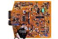
RGB, 3개 신호를 전력 처리하기 위함.
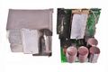
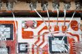
- Sanyo STK181B
- 분해
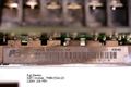
- 세부 사진
방열판 알루미늄에 본딩
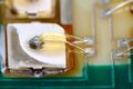
금속 방열판 붙이고, Al wedge 본딩
910오옴 8개 직렬?
절연층이 매우 두껍다.
- 보드에서
- Mitsubishi EUM-1491A 14" CRT 모니터
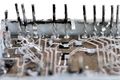
- 모터용 주파수 가변 에서
- 미쯔비시 FR-D720 인버터, 2015/10/06 촬영
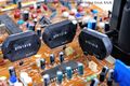
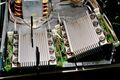
- LS산전 iG5A 인버터에서,
- Fusji Electric, IGBT 모듈, 7MBR15SA120, 1200V 15A PIM
- 외관
방열방법
라벨
- 크기 및 회로도
크기
회로도
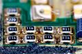
- SMD 부품
SMD 부품
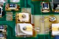
- 칩 와이어 본딩
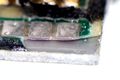
- 두께, 금속 방열판 두께 4mm, 세라믹기판 두께 0.4mm
- 가열해서 Direct bonded copper(DBC) substrates를 방열판에서 뜯어냄
양면 DBC
다이오드 칩이 분리
- 외관
- Fusji Electric, IGBT 모듈, 7MBR15SA120, 1200V 15A PIM
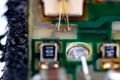
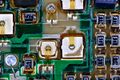
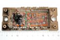
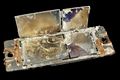
- LS산전 SV-iC5 인버터, SV008iC5-2
- in 200-230V 6.6A 3상 50/60Hz, out 0~input 5A 3상, 0.01~400Hz, 1HP 0.75kW(D), 2016/02/14 사진
- Intelligent Power Module(IPM) 뚜껑 실링
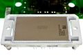
Vinco 회사 제품
- 리드쪽 수지 케이스를 잘라내면
오른쪽이 고장났다.
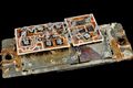
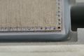
- PCB와 연결되는 납땜용 리드 관찰
스트레스 해소를 위한 리드 구부림
전극 두께 및 리드 접속
- 실리콘 젤을 통해 본, Al 웨지 와이어본딩 관찰
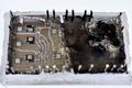
- 불꽃 방전으로 검게 변한 부위
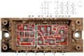
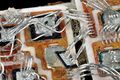
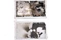
- 실리콘 젤을 제거한 후, DBC 기판 표면 관찰
- NTC 온도센서
- 미쯔비시 FR-D720 인버터, 2015/10/06 촬영
- 전력조정기
- 16/02/23 TPR 전력조정기
- 사진
- SCR에서 자세히 분석
- 사진
- 16/02/23 TPR 전력조정기
- 모터 드라이브
- 창민 SR2000 면저항측정기, 모터(4phase, Japan Servo 회사, KY시리즈, DC 3V, 4-phase, 0.45도/step) 드라이브 모듈
- 세트
- 분해
- 세트
- 창민 SR2000 면저항측정기, 모터(4phase, Japan Servo 회사, KY시리즈, DC 3V, 4-phase, 0.45도/step) 드라이브 모듈
- 대전력 SSR
- 사진
- Omron SSR
- Omron SSR
- 리니어 레귤레이터용
- HP 6652A DC 전원공급기
같은 전력모듈 2개를 사용
- HP 6652A DC 전원공급기


