"Yokogawa LR4110 펜레코더"의 두 판 사이의 차이
잔글 (Togotech님이 LR4110 문서를 Yokogawa LR4110 펜레코더 문서로 이동했습니다) |
잔글 |
||
| 1번째 줄: | 1번째 줄: | ||
| − | LR4110 | + | Yokogawa LR4110 펜레코더 |
| − | |||
| − | |||
<ol> | <ol> | ||
<li> [[전자부품]] | <li> [[전자부품]] | ||
| 7번째 줄: | 5번째 줄: | ||
<li> [[기록계]] | <li> [[기록계]] | ||
<ol> | <ol> | ||
| − | <li> [[LR4110]] | + | <li> [[Yokogawa LR4110 펜레코더]] - 이 페이지 |
| − | |||
</ol> | </ol> | ||
</ol> | </ol> | ||
| 15번째 줄: | 12번째 줄: | ||
<li>자료 | <li>자료 | ||
<ol> | <ol> | ||
| − | <li>LR4110, 371145-B-0, 1991년 산 | + | <li>LR4110, 모델:371145 접미사(suffix) -B-0, 1991년 산 |
<li>사용자 설명서 - 162p | <li>사용자 설명서 - 162p | ||
</ol> | </ol> | ||
| 26번째 줄: | 23번째 줄: | ||
<li>2014/04/19 | <li>2014/04/19 | ||
<gallery> | <gallery> | ||
| − | image:pen_recorder1_004.jpg | + | image:pen_recorder1_004.jpg | 전면 |
| − | image:pen_recorder1_005.jpg | + | image:pen_recorder1_005.jpg | 후면, 입력 4채널 |
| − | image:pen_recorder1_006.jpg | + | image:pen_recorder1_006.jpg | 라벨 |
</gallery> | </gallery> | ||
</ol> | </ol> | ||
| 42번째 줄: | 39번째 줄: | ||
image:pen_recorder2_003.jpg | image:pen_recorder2_003.jpg | ||
</gallery> | </gallery> | ||
| + | <li> [[VFD]] | ||
| + | <ol> | ||
<li>VFD 보드. Futaba M20SD05B | <li>VFD 보드. Futaba M20SD05B | ||
<gallery> | <gallery> | ||
| − | image:pen_recorder1_002.jpg | + | image:pen_recorder1_002.jpg | 좌상단에 약 50V를 출력시키는 전원장치 |
| − | image:pen_recorder1_003.jpg | VFD | + | image:pen_recorder1_003.jpg | VFD 4개 사용 |
| − | image:pen_recorder1_007.jpg | + | </gallery> |
| + | <li>VFD용 전원장치, 1P50A 156-01 | ||
| + | <gallery> | ||
| + | image:pen_recorder1_008.jpg | 부품면 | ||
| + | image:pen_recorder1_009.jpg | 납땜면 | ||
| + | </gallery> | ||
| + | <li>Dot Matrix Type VFD, 20-SD-05G(20자 1줄) 4개(4채널이므로)를 사용함. | ||
| + | <ol> | ||
| + | <li>앞면 | ||
| + | <gallery> | ||
| + | image:pen_recorder1_007.jpg | 앞면에서 도트 배열 | ||
</gallery> | </gallery> | ||
| − | <li> | + | <li>뒷면에서 관찰 |
<gallery> | <gallery> | ||
| − | image: | + | image:vfd01_001.jpg |
| − | image: | + | image:vfd01_002.jpg |
| + | image:vfd01_003.jpg | ||
| + | image:vfd01_004.jpg | ||
</gallery> | </gallery> | ||
| + | </ol> | ||
| + | </ol> | ||
</ol> | </ol> | ||
<li>CPU 보드 | <li>CPU 보드 | ||
| 58번째 줄: | 71번째 줄: | ||
image:pen_recorder_cpu_001.jpg | NEC uPD70208L-8, NEC V40 [[MPU]] family | image:pen_recorder_cpu_001.jpg | NEC uPD70208L-8, NEC V40 [[MPU]] family | ||
image:pen_recorder_cpu_002.jpg | Fujitsu MB3771 Power Supply Monitor | image:pen_recorder_cpu_002.jpg | Fujitsu MB3771 Power Supply Monitor | ||
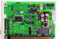
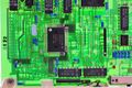
| − | image:pen_recorder_cpu_003.jpg | | + | image:pen_recorder_cpu_003.jpg | [[RTC]], [[실린더형 금속패키지 튜닝포크 수정진동자]], [[운모 커패시터]] |
</gallery> | </gallery> | ||
<li>입력보드, 4채널이므로 4장을 꼽는다. | <li>입력보드, 4채널이므로 4장을 꼽는다. | ||
| 65번째 줄: | 78번째 줄: | ||
<gallery> | <gallery> | ||
image:pen_recorder1_010.jpg | 보드 이름 마킹: B9619P V | image:pen_recorder1_010.jpg | 보드 이름 마킹: B9619P V | ||
| + | </gallery> | ||
| + | <li>아날로그 파트를 위한 [[실드 깡통]] | ||
| + | <gallery> | ||
image:pen_recorder_input_001.jpg | image:pen_recorder_input_001.jpg | ||
image:pen_recorder_input_002.jpg | image:pen_recorder_input_002.jpg | ||
</gallery> | </gallery> | ||
| − | <li>앞면 1/2 - | + | <li>앞면 1/2 - [[실드 깡통]]을 뜯어낸 후, 아날로그부 |
<gallery> | <gallery> | ||
image:pen_recorder_input_004.jpg | image:pen_recorder_input_004.jpg | ||
| − | image:pen_recorder1_012.jpg | | + | image:pen_recorder1_012.jpg | IC 5가지 설명 |
image:pen_recorder_input_005.jpg | image:pen_recorder_input_005.jpg | ||
image:pen_recorder_input_006.jpg | image:pen_recorder_input_006.jpg | ||
| 79번째 줄: | 95번째 줄: | ||
image:pen_recorder1_011.jpg | image:pen_recorder1_011.jpg | ||
image:pen_recorder_input_003.jpg | image:pen_recorder_input_003.jpg | ||
| − | image:pen_recorder_input_007.jpg | MA6208D ADC | + | image:pen_recorder_input_007.jpg | MA6208D [[ADC]] |
image:pen_recorder_input_008.jpg | image:pen_recorder_input_008.jpg | ||
| − | image:pen_recorder_input_010.jpg | + | image:pen_recorder_input_010.jpg | LM339 |
</gallery> | </gallery> | ||
<li>Panasonic(삼각형마크) MA6208D [[ADC]] | <li>Panasonic(삼각형마크) MA6208D [[ADC]] | ||
| 131번째 줄: | 147번째 줄: | ||
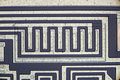
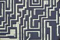
<li> [[가드링]] | <li> [[가드링]] | ||
<gallery> | <gallery> | ||
| − | image:pen_recorder_input_013.jpg | 입력단자와 연결되는 Toroidal core를 사용한 [[CMF]] | + | image:pen_recorder_input_013.jpg | 측정 입력단자와 연결되는 Toroidal core를 사용한 [[CMF]] |
image:pen_recorder_input_014.jpg | image:pen_recorder_input_014.jpg | ||
image:pen_recorder_input_015.jpg | image:pen_recorder_input_015.jpg | ||
image:pen_recorder_input_017.jpg | 잘 보이는 [[가드링]] | image:pen_recorder_input_017.jpg | 잘 보이는 [[가드링]] | ||
</gallery> | </gallery> | ||
| − | <li>[[ | + | <li> [[구리]]판을 사용한 [[등온 블록]] |
<gallery> | <gallery> | ||
image:pen_recorder_input_011.jpg | 왼쪽 별도 PCB에는 상온온도센서가 있다. | image:pen_recorder_input_011.jpg | 왼쪽 별도 PCB에는 상온온도센서가 있다. | ||
| 280번째 줄: | 296번째 줄: | ||
image:pen_recorder5_020.jpg | image:pen_recorder5_020.jpg | ||
</gallery> | </gallery> | ||
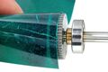
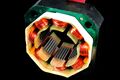
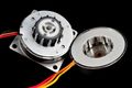
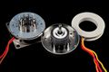
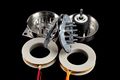
| − | <li>영구자석 회전자 | + | <li>[[영구자석]] 회전자 |
<gallery> | <gallery> | ||
| − | image:pen_recorder5_017.jpg | 자석 두 개를 붙였다. (부품 표주화?) | + | image:pen_recorder5_017.jpg | [[자석]] 두 개를 붙였다. (부품 표주화?) |
image:pen_recorder5_018.jpg | image:pen_recorder5_018.jpg | ||
image:pen_recorder5_019.jpg | 4극 | image:pen_recorder5_019.jpg | 4극 | ||
| 334번째 줄: | 350번째 줄: | ||
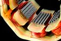
image:pen_recorder6_007.jpg | image:pen_recorder6_007.jpg | ||
image:pen_recorder6_005.jpg | 24극 | image:pen_recorder6_005.jpg | 24극 | ||
| − | image:pen_recorder6_008.jpg | | + | image:pen_recorder6_008.jpg | [[자석]]과 축이 미끄러지지 않게, [[자석]]에 홈을 두고 사출 |
image:pen_recorder6_009.jpg | image:pen_recorder6_009.jpg | ||
</gallery> | </gallery> | ||
| 355번째 줄: | 371번째 줄: | ||
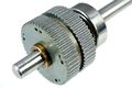
image:pen_recorder7_002.jpg | Nippon Pulse Motor, 스텝퍼모터, PF42-48E1 50ohm, Gear Ratio 1/25 | image:pen_recorder7_002.jpg | Nippon Pulse Motor, 스텝퍼모터, PF42-48E1 50ohm, Gear Ratio 1/25 | ||
</gallery> | </gallery> | ||
| − | <li>스테퍼모터와 | + | <li>스테퍼모터와 [[감속기]]를 분리함 |
<gallery> | <gallery> | ||
image:pen_recorder7_006.jpg | image:pen_recorder7_006.jpg | ||
image:pen_recorder7_007.jpg | image:pen_recorder7_007.jpg | ||
</gallery> | </gallery> | ||
| − | <li>25:1 감속 기어 | + | <li>25:1 감속 [[기어]] |
<gallery> | <gallery> | ||
| − | image:pen_recorder7_008.jpg | | + | image:pen_recorder7_008.jpg | [[그리스]] 듬뿍 |
image:pen_recorder7_010.jpg | image:pen_recorder7_010.jpg | ||
image:pen_recorder7_009.jpg | 3군데 접촉 지점에서 회전비 12/30 x 12/30 x 10/40 = 1/25 | image:pen_recorder7_009.jpg | 3군데 접촉 지점에서 회전비 12/30 x 12/30 x 10/40 = 1/25 | ||
</gallery> | </gallery> | ||
| − | <li>두 | + | <li>두 [[기어]]를 결합하여 고정하는 방법 |
<gallery> | <gallery> | ||
image:pen_recorder7_011.jpg | image:pen_recorder7_011.jpg | ||
image:pen_recorder7_012.jpg | image:pen_recorder7_012.jpg | ||
| − | image:pen_recorder7_013.jpg | + | image:pen_recorder7_013.jpg | 가장자리 6군데를 펀칭해서 직경을 늘렸다. |
</gallery> | </gallery> | ||
</ol> | </ol> | ||
<li>각종 회전축 고정 | <li>각종 회전축 고정 | ||
<ol> | <ol> | ||
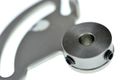
| − | <li> | + | <li>베어링 |
<gallery> | <gallery> | ||
image:pen_recorder8_001.jpg | image:pen_recorder8_001.jpg | ||
</gallery> | </gallery> | ||
| − | <li>고정 1 | + | <li>고정 1 - 직경이 커, 7군데 가장자리를 펀칭해서 직경을 늘렸다. |
<gallery> | <gallery> | ||
image:pen_recorder8_002.jpg | image:pen_recorder8_002.jpg | ||
image:pen_recorder8_003.jpg | image:pen_recorder8_003.jpg | ||
</gallery> | </gallery> | ||
| − | <li>고정 2,3,4 | + | <li>고정 2,3,4 - 90도 간격으로 가장자리를 펀칭해서 직경을 늘렸다. |
<gallery> | <gallery> | ||
image:pen_recorder8_004.jpg | image:pen_recorder8_004.jpg | ||
image:pen_recorder8_005.jpg | image:pen_recorder8_005.jpg | ||
| + | image:pen_recorder8_007.jpg | ||
| + | </gallery> | ||
| + | <li>고정 5 - 중심부위를 펀칭하여 직경을 늘렸다. | ||
| + | <gallery> | ||
image:pen_recorder8_006.jpg | image:pen_recorder8_006.jpg | ||
| − | |||
</gallery> | </gallery> | ||
| − | <li>고정 6 | + | <li>고정 6, 억지끼워 맞춤을 할 때, 프레스 타발 방향을 고려하여 삽입 방향을 결정한다. |
<gallery> | <gallery> | ||
image:pen_recorder8_008.jpg | image:pen_recorder8_008.jpg | ||
| 403번째 줄: | 422번째 줄: | ||
image:pen_recorder9_002.jpg | image:pen_recorder9_002.jpg | ||
image:pen_recorder9_003.jpg | image:pen_recorder9_003.jpg | ||
| − | image:pen_recorder9_004.jpg | + | image:pen_recorder9_004.jpg | 4개 펜이 서로 부딪히지 않게 스페이서 길이가 다르다. |
</gallery> | </gallery> | ||
</ol> | </ol> | ||
</ol> | </ol> | ||
2025년 1월 17일 (금) 12:31 기준 최신판
Yokogawa LR4110 펜레코더
- 전자부품
- 기록계
- Yokogawa LR4110 펜레코더 - 이 페이지
- 기록계
- Yokogawa LR4110 펜레코더
- 자료
- LR4110, 모델:371145 접미사(suffix) -B-0, 1991년 산
- 사용자 설명서 - 162p
- 외형
- 2004/01/25
- 2014/04/19
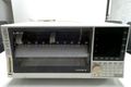
전면
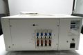
후면, 입력 4채널
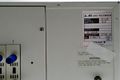
라벨
- 2004/01/25
- 디스플레이
- 앞면, 뒷면
- 보드
- VFD
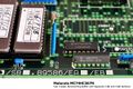
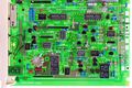
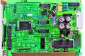
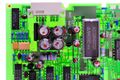
- VFD 보드. Futaba M20SD05B
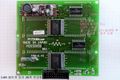
좌상단에 약 50V를 출력시키는 전원장치
VFD 4개 사용
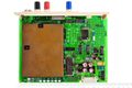
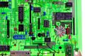
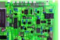
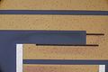
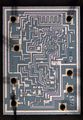
- VFD용 전원장치, 1P50A 156-01
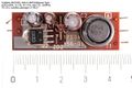
부품면
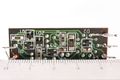
납땜면
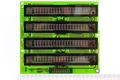
- Dot Matrix Type VFD, 20-SD-05G(20자 1줄) 4개(4채널이므로)를 사용함.
- 앞면
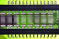
앞면에서 도트 배열
- 뒷면에서 관찰
- 앞면
- VFD 보드. Futaba M20SD05B
- 앞면, 뒷면
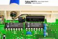
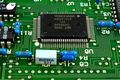
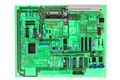
- CPU 보드
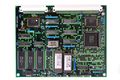
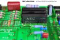
NEC uPD70208L-8, NEC V40 MPU family
Fujitsu MB3771 Power Supply Monitor
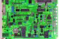
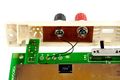
- 입력보드, 4채널이므로 4장을 꼽는다.
- 앞면, 뒷면
보드 이름 마킹: B9619P V
- 아날로그 파트를 위한 실드 깡통
- 앞면 1/2 - 실드 깡통을 뜯어낸 후, 아날로그부
IC 5가지 설명
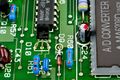
- 앞면 1/2 - 디지털부
MA6208D ADC
LM339
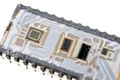
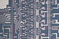
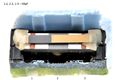
- Panasonic(삼각형마크) MA6208D ADC
- 외관
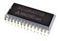
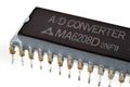
세라믹 뚜껑 주위에 에폭시를 부어 접착함.
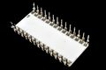
밑면
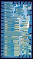
- 리드 제거
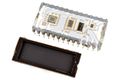
세라믹 캐비티 뚜껑
다이 4개 사용, 왼쪽에 AD 회사 마크가 보인다.
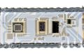
왼쪽부터 다이1,2,3,4이라고 하자.
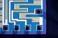
- 다이1
MSM 71065 OKi
- 다이2
AN 6809 N1A
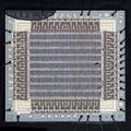
- 다이3 - 레이저 트리밍된 네트워크 저항
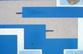
top hat plunge cut
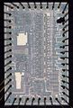
- 다이4
MEC 6977, Matsushita Electronics Corporation 약자인 듯
- 외관
- 압전체 레조네이터
무라타 8000A
단판 C를 내장하고 있다. 측정하니 8MHz 맞다.
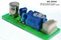
- 전압표준
LT1009CZ. 2.5V +- 5mV 초기 정확도, 25ppm/'C, 8-bit ADC용
- 가드링
- 구리판을 사용한 등온 블록
왼쪽 별도 PCB에는 상온온도센서가 있다.
- 다이오드기반 온도센서
- 사진
2SC943, TC 사용을 하려면 반드시 주변 온도를 측정해야 하므로
- 온도에 따른 Vf 측정 데이터
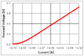
전류에 따른 Vf
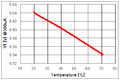
온도에 따른 Vf. 약 -2mV/'C 나온다.
- 사진
- 앞면, 뒷면
- 도트매트릭스 프린터
- 헤드 분해 -> 도트매트릭스 프린터 참조
- 제어보드
Hitachi HA13408 9-ch Power Driver dot matrix printer head
NEC uPA1526H 4ch Power MOSFET array
- 38-pin 메모리카드를 사용한다.
- 기구 본체 분해
- 차트 X
- X축 - 종이를 이송한다.
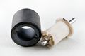
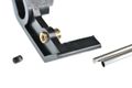
- 도트매트릭스 프린터 헤드 Y-이동 스텝퍼모터 - VEXTA, stepping motor, Oriental Motor Co., Ltd, model:C4926-9012, 2-phase 1.8deg/step DC12V 0.31A
- 외관
- 분해
코일을 코어에 하나씩 감아야 한다.
- 외관
- 도트매트릭스 프린터 헤드 Y-이동
- 헤드를 종이에 밀착하고 간격을 벌리고
헤드를 앞뒤로
편심가공
- X축 - 종이를 이송한다.
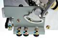
- 차트 Y
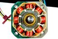
- AC서보 모터용 드라이브 보드
- 펜 이동(정밀해야 함)용 AC 서보 모터(제조회사, 모델 표기 없음) - 4색 펜이므로 4개 사용
- 펜 다운
- 메커니즘
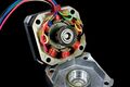
- 스테퍼모터를 이용하여 4개의 펜을 올리고 내린다.
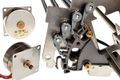
Nippon Pulse Motor, 스텝퍼모터, PF42-48E1 50ohm
12개 이빨, 맞물리면 24개
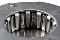
미리 원통 내부연마(보링 boring)한 듯

24극
- 메커니즘
- 차트 종이 이송(Y축)
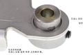
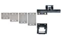
- 각종 회전축 고정
- 베어링
- 고정 1 - 직경이 커, 7군데 가장자리를 펀칭해서 직경을 늘렸다.
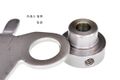
- 고정 2,3,4 - 90도 간격으로 가장자리를 펀칭해서 직경을 늘렸다.
- 고정 5 - 중심부위를 펀칭하여 직경을 늘렸다.
- 고정 6, 억지끼워 맞춤을 할 때, 프레스 타발 방향을 고려하여 삽입 방향을 결정한다.
프레스 타발 방향을 고려해야 함
- 베어링
- 펜 고정
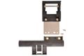
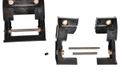
4개 펜이 서로 부딪히지 않게 스페이서 길이가 다르다.
- 자료


