"PTC-200"의 두 판 사이의 차이
(새 문서: PTC-200 펠티어 <ol> <li>링크 <ol> <li> 전자부품 <ol> <li> 펠티어 </ol> </ol> <li>MJ Research, PTC-200 Peltier Thermal Cycler <ol> <li>19/10/22 - 10p <li>외관 <ga...) |
|||
| 6번째 줄: | 6번째 줄: | ||
<ol> | <ol> | ||
<li> [[펠티어]] | <li> [[펠티어]] | ||
| + | <ol> | ||
| + | <li> SCNT FC-2410 Freeze & Hot Controller [[SCNT FC-2410]] | ||
| + | <li> MJ Research, PTC-200 Peltier Thermal Cycler [[PTC-200]] | ||
| + | <li> 미쓰미 PLCN [[PLCN]] | ||
| + | </ol> | ||
</ol> | </ol> | ||
</ol> | </ol> | ||
| 76번째 줄: | 81번째 줄: | ||
<gallery> | <gallery> | ||
image:ptc200_024.jpg | image:ptc200_024.jpg | ||
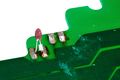
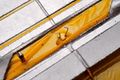
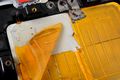
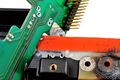
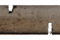
| − | image:ptc200_024_001.jpg | 구리 전극을 단자로 연결하는 방법 | + | image:ptc200_024_001.jpg | F-PCB 구리 전극을 단자로 연결하는 방법 |
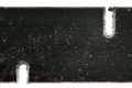
image:ptc200_025.jpg | 샘플 홀더 뚜껑 | image:ptc200_025.jpg | 샘플 홀더 뚜껑 | ||
</gallery> | </gallery> | ||
| 90번째 줄: | 95번째 줄: | ||
image:ptc200_030.jpg | image:ptc200_030.jpg | ||
image:ptc200_031.jpg | 약 5.5오옴 | image:ptc200_031.jpg | 약 5.5오옴 | ||
| − | |||
image:ptc200_032.jpg | image:ptc200_032.jpg | ||
| + | </gallery> | ||
| + | <li>히터 앞 뒤면 온도 측정 | ||
| + | <gallery> | ||
| + | image:ptc200_031_001.jpg | 12V 인가시. 방사율 때문에(?) 발열체가 더 낮게 측정된다. | ||
| + | image:ptc200_031_002.jpg | 면적에서 +-1도씨 편차, 히터 반대면(시료와 닿은 표면)은 샘플홀더 형태가 관찰된다.(anodizing이 벗겨져 방사율이 달라져?) | ||
| + | </gallery> | ||
| + | <li>V-I 특성 | ||
| + | <gallery> | ||
| + | image:heater_graphite01_001.png | (-)온도계수를 갖는다. | ||
</gallery> | </gallery> | ||
</ol> | </ol> | ||
| 105번째 줄: | 118번째 줄: | ||
image:ptc200_037.jpg | image:ptc200_037.jpg | ||
image:ptc200_038.jpg | image:ptc200_038.jpg | ||
| − | image:ptc200_039.jpg | + | image:ptc200_039.jpg | Bismuth telluride(Bi2Te3)로 추정 |
</gallery> | </gallery> | ||
<li>Peltier 소자 자세히 | <li>Peltier 소자 자세히 | ||
| 115번째 줄: | 128번째 줄: | ||
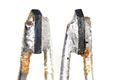
image:ptc200_049_001.jpg | 충격을 가하니 쉽게 떨어져 | image:ptc200_049_001.jpg | 충격을 가하니 쉽게 떨어져 | ||
image:ptc200_049_002.jpg | image:ptc200_049_002.jpg | ||
| + | </gallery> | ||
| + | <li>공기중에 전류를 인가하면 | ||
| + | <gallery> | ||
| + | image:ptc200_049_003.jpg | 뜨거워지는 면 | ||
| + | image:ptc200_049_004.jpg | 차거워지는 면(반대편에서 가해지는 열전달 때문에, 덜 뜨거워진다.) | ||
</gallery> | </gallery> | ||
<li>물이 고여 단락???? | <li>물이 고여 단락???? | ||
| 121번째 줄: | 139번째 줄: | ||
image:ptc200_036.jpg | image:ptc200_036.jpg | ||
</gallery> | </gallery> | ||
| − | <li>아랫쪽 방열판 온도 측정 센서 | + | <li>아랫쪽 방열판 [[NTC]] 온도 측정 센서 |
<gallery> | <gallery> | ||
image:ptc200_040.jpg | image:ptc200_040.jpg | ||
image:ptc200_041.jpg | image:ptc200_041.jpg | ||
| + | image:ptc200_041_001.jpg | 상단 한쪽 꼭지점을 갈아내어 저항값을 높이는 트리밍을 했다. | ||
image:ptc200_042.jpg | 써미스터 온도 센서 부착 구멍에 발라진 방열 그리스 | image:ptc200_042.jpg | 써미스터 온도 센서 부착 구멍에 발라진 방열 그리스 | ||
</gallery> | </gallery> | ||
| 135번째 줄: | 154번째 줄: | ||
image:ptc200_043.jpg | image:ptc200_043.jpg | ||
image:ptc200_044.jpg | image:ptc200_044.jpg | ||
| + | image:ptc200_044_001.jpg | 7A125V, 130'CR4, 213, UMI | ||
</gallery> | </gallery> | ||
| − | <li>중앙에 NTC 10k 오옴 온도센서 | + | <li>중앙에 [[NTC]] 10k 오옴 온도센서 |
<gallery> | <gallery> | ||
image:ptc200_051.jpg | image:ptc200_051.jpg | ||
| 142번째 줄: | 162번째 줄: | ||
image:ptc200_053.jpg | image:ptc200_053.jpg | ||
image:ptc200_054.jpg | image:ptc200_054.jpg | ||
| + | image:ptc200_054_001.jpg | 상단부위를 경사지게 갈아내어 저항값을 높이는 트리밍을 ㅤㅎㅒㅆ다. | ||
</gallery> | </gallery> | ||
| − | <li>대각선 측면에 NTC 10k 오옴 온도센서 두 개 | + | <li>대각선 측면에 [[NTC]] 10k 오옴 온도센서 두 개 |
<gallery> | <gallery> | ||
image:ptc200_055.jpg | image:ptc200_055.jpg | ||
| 163번째 줄: | 184번째 줄: | ||
<gallery> | <gallery> | ||
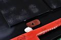
image:ptc200_062.jpg | 고무 가스켓 | image:ptc200_062.jpg | 고무 가스켓 | ||
| − | image:ptc200_063.jpg | 중앙에 NTC-10k 온도센서를 꼽기 위한 자리 | + | image:ptc200_063.jpg | 중앙에 [[NTC]]-10k 온도센서를 꼽기 위한 자리 |
</gallery> | </gallery> | ||
</ol> | </ol> | ||
| 172번째 줄: | 193번째 줄: | ||
image:ptc200_079.jpg | image:ptc200_079.jpg | ||
</gallery> | </gallery> | ||
| + | <li>AC입력단에 직렬로 사용된 [[NTC]] | ||
| + | <ol> | ||
| + | <li>외형 | ||
| + | <gallery> | ||
| + | image:ptc200_079_003_001.jpg | 로고를 보면, Ametherm회사(종래? Ketema, Rodan Division), , RTI, SURGE-GARD, SG40, NTC, 10ohm@25'C 8A | ||
| + | image:ptc200_079_003_002.jpg | 고장나 있음. | ||
| + | </gallery> | ||
| + | <li>팽윤제 12시간 + 코팅 뜯어내고 + 질산에 2분 + 알루미나 연마제 | ||
| + | <gallery> | ||
| + | image:ptc200_079_003_003.jpg | 약 13오옴으로 측정됨. | ||
| + | image:ptc200_079_003_004.jpg | ||
| + | image:ptc200_079_003_005.jpg | ||
| + | </gallery> | ||
| + | </ol> | ||
| + | <li>전원단에 상시 방전용 1k오옴 저항이 뜨거워져 PCB 쪽으로 단열 방법 | ||
| + | <gallery> | ||
| + | image:ptc200_079_004_001.jpg | RCD160 1kohm 5%, all-welded wirewound construction | ||
| + | image:ptc200_079_004_002.jpg | RCD Components Inc, 5W, 275'C까지, Hi-temp silicone coating | ||
| + | </gallery> | ||
| + | <li>인덕터 - 모두 7개 | ||
| + | <ol> | ||
| + | <li>외형 | ||
| + | <gallery> | ||
| + | image:ptc200_079_005_001.jpg | ||
| + | image:ptc200_079_005_002.jpg | ||
| + | </gallery> | ||
| + | <li>코어 구조 | ||
| + | <gallery> | ||
| + | image:ptc200_079_005_003.jpg | ||
| + | image:ptc200_079_005_004.jpg | toroid core 두 개를 붙였다. 이름 모르겠다. 왜 두 개를 붙였는지 모르겠다. | ||
| + | </gallery> | ||
| + | <li>코어를 깨보면 | ||
| + | <gallery> | ||
| + | image:ptc200_079_005_005.jpg | ||
| + | image:ptc200_079_005_006.jpg | 두 재료가 다르다. | ||
| + | </gallery> | ||
| + | </ol> | ||
| + | <li>전해C | ||
| + | <gallery> | ||
| + | image:ptc200_079_006_001.jpg | 전극방향 표시(+를 표시할수도 있다.) | ||
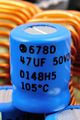
| + | image:ptc200_079_006_002.jpg | 검정색잉크를 열로 눌러 , 105도씨, Vishay Sprague 678D-series | ||
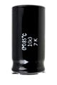
| + | image:ptc200_079_006_003.jpg | 85도씨 | ||
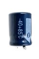
| + | image:ptc200_079_006_004.jpg | -40도~+85도씨 | ||
| + | </gallery> | ||
| + | <li>전류 제한용 저저항 | ||
| + | <ol> | ||
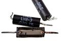
| + | <li>6개 있음. Dale, LVR-3, 0.020오옴 1% 편차, Metal strip 저항체 구조 | ||
| + | <gallery> | ||
| + | image:ptc200_079_001_001.jpg | 불에 빨갛게 태워도 불이 붙지 않는 수지.(유리섬유 함량이 매우 높은 듯) | ||
| + | image:ptc200_079_001_002.jpg | 블레이드 절삭 뒷면 | ||
| + | image:ptc200_079_001_003.jpg | 블레이드 절삭 앞면 | ||
| + | image:ptc200_079_001_004.jpg | 절삭면이 상당히 많이 테이퍼져 있음. | ||
| + | image:ptc200_079_001_005.jpg | ||
| + | </gallery> | ||
| + | <li>2개 있음 | ||
| + | <gallery> | ||
| + | image:ptc200_076.jpg | 1오옴, 금색 5% | ||
| + | image:axial_r15_001.jpg | 불에 빨갛게 태운 절연피막(전혀 타지 않음)을 벗기고. | ||
| + | image:axial_r15_002.jpg | 3W 제품과 크기 비교 | ||
| + | image:axial_r15_003.jpg | ||
| + | image:axial_r15_004.jpg | 나선 컷 확대 | ||
| + | </gallery> | ||
| + | </ol> | ||
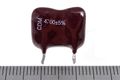
| + | <li>[[운모C]], CDM(Cornell Dubilier Electronics;CDE) | ||
| + | <ol> | ||
| + | <li>외형 | ||
| + | <gallery> | ||
| + | image:ptc200_079_002_001.jpg | 4700pF, 5%, 1000V | ||
| + | image:ptc200_079_002_002.jpg | ||
| + | image:ptc200_079_002_003.jpg | 열풍을 가해서 코팅 에폭시를 뜯어냄(내부는 타거나 녹지 않음) | ||
| + | </gallery> | ||
| + | <li>분해 | ||
| + | <gallery> | ||
| + | image:ptc200_079_002_004.jpg | (튼튼한)리드 고정 방법, 내부 구조 | ||
| + | image:ptc200_079_002_005.jpg | ||
| + | image:ptc200_079_002_006.jpg | ||
| + | image:ptc200_079_002_007.jpg | 운모판 중심에 전극을 형성하고, 좌우 교대로 금속 포일을 1/3 끼워넣어 접촉함. | ||
| + | </gallery> | ||
| + | </ol> | ||
<li>방열판 클립 | <li>방열판 클립 | ||
<gallery> | <gallery> | ||
| 181번째 줄: | 281번째 줄: | ||
</gallery> | </gallery> | ||
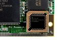
<li>FET, 레귤레이터, 정류기 등 | <li>FET, 레귤레이터, 정류기 등 | ||
| + | <ol> | ||
| + | <li>FET | ||
<gallery> | <gallery> | ||
image:ptc200_069.jpg | BUZ11 FET 5개, 7815 레귤레이터 | image:ptc200_069.jpg | BUZ11 FET 5개, 7815 레귤레이터 | ||
image:ptc200_070.jpg | BUZ11 | image:ptc200_070.jpg | BUZ11 | ||
image:ptc200_071.jpg | image:ptc200_071.jpg | ||
| − | image:ptc200_072.jpg | BUZ11, N-Channel Power MOSFET 50V, 30A, | + | image:ptc200_072.jpg | BUZ11, N-Channel Power MOSFET 50V, 30A, 40mohm |
| − | |||
image:ptc200_074.jpg | SAMSUNG KA7805, BUZ11 | image:ptc200_074.jpg | SAMSUNG KA7805, BUZ11 | ||
| + | </gallery> | ||
| + | <li>정류기 | ||
| + | <gallery> | ||
image:ptc200_075.jpg | MBR1060, Schottky Barrier Rectifier, 10A 60V | image:ptc200_075.jpg | MBR1060, Schottky Barrier Rectifier, 10A 60V | ||
| + | image:ptc200_073.jpg | MUR820 Ultrafast Recovery Time Rectifier, 200V 8A | ||
image:ptc200_076.jpg | MUG820G | image:ptc200_076.jpg | MUG820G | ||
| + | </gallery> | ||
| + | <li>FET on/off control cicuit module(Gate Drive Circuit) | ||
| + | <gallery> | ||
image:ptc200_077.jpg | image:ptc200_077.jpg | ||
| − | image:ptc200_078.jpg | + | image:ptc200_078.jpg |
| + | image:ptc200_078_001.jpg | ||
</gallery> | </gallery> | ||
| + | </ol> | ||
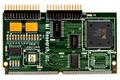
<li>CPU 보드 | <li>CPU 보드 | ||
<gallery> | <gallery> | ||
2020년 1월 26일 (일) 19:27 기준 최신판
PTC-200 펠티어
- 링크
- 전자부품
- 펠티어
- SCNT FC-2410 Freeze & Hot Controller SCNT FC-2410
- MJ Research, PTC-200 Peltier Thermal Cycler PTC-200
- 미쓰미 PLCN PLCN
- 펠티어
- 전자부품
- MJ Research, PTC-200 Peltier Thermal Cycler
- 19/10/22 - 10p
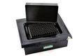
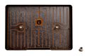
- 외관
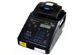
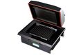
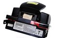
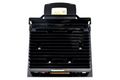
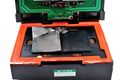
MJ Research, PTC-200 Peltier Thermal Cycler
MJ Research, PTC-200
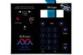
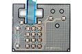
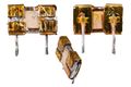
- 디스플레이 및 키패드
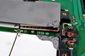
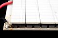
- 키패드
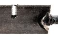
은,카본 전극을 단자로 연결하는 방법
- LCD 모듈
- 키패드
- 전원
- Schaffner FN 286-6-06
- TOKIN SC Coil SC-04-200JV
- Panasonic ZNR varistor, Panasonic ECQ-UV box capacitor(Interference Suppression Capacitor. Metallized Polyester)
- MICRO SWITCH, FREEPORT. ILL. USA, Micro Switches -> Honeywell
- Schaffner FN 286-6-06
- Alpha Unit Block Assembly for PTC DNA Engine Systems
- 모듈
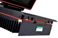
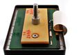
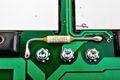
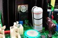
밑을 향하고 있는 방열판
방열판에서 샘플홀더를 고정하는 위 나사
- 이 모듈과 전기 연결하는 커넥터를 꼽기 위한 가이드
- 단열, 실링
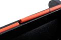
뚜껑용
- 샘플 홀더를 위에서 눌러 기밀성을 유지하도록 높이 조절
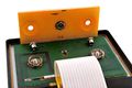
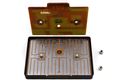
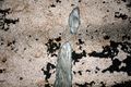
F-PCB 구리 전극을 단자로 연결하는 방법
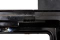
샘플 홀더 뚜껑
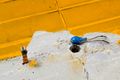
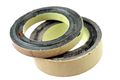
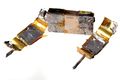
- 뚜껑용 히터 연결 방법
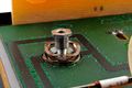
스프링 와셔
온도센서
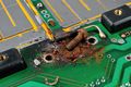
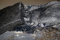
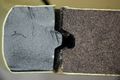
- 히터 - natural graphite sheet 로 추정
약 5.5오옴
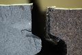
- 히터 앞 뒤면 온도 측정
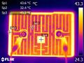
12V 인가시. 방사율 때문에(?) 발열체가 더 낮게 측정된다.
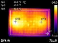
면적에서 +-1도씨 편차, 히터 반대면(시료와 닿은 표면)은 샘플홀더 형태가 관찰된다.(anodizing이 벗겨져 방사율이 달라져?)
- V-I 특성
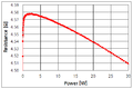
(-)온도계수를 갖는다.
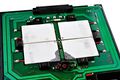
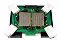
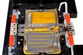
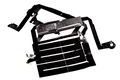
- 모듈
- 샘플 홀더 쪽
- 위쪽이 샘플 홀더, 아랫쪽은 방열판
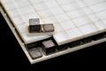
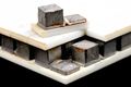
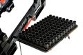
- TE(thermoelectric;Peltier) cooling modules 4개 사용
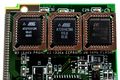
Bismuth telluride(Bi2Te3)로 추정
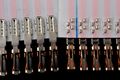
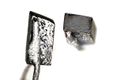
- Peltier 소자 자세히
충격을 가하니 쉽게 떨어져
- 공기중에 전류를 인가하면
- ptc200 049 003.jpg
뜨거워지는 면
- ptc200 049 004.jpg
차거워지는 면(반대편에서 가해지는 열전달 때문에, 덜 뜨거워진다.)
- 물이 고여 단락????
- 아랫쪽 방열판 NTC 온도 측정 센서
상단 한쪽 꼭지점을 갈아내어 저항값을 높이는 트리밍을 했다.
써미스터 온도 센서 부착 구멍에 발라진 방열 그리스
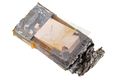
- PCB 위면, 아랫면 표시 방법
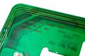
If you can read this the pcb is on upside down (이 글씨를 읽을 수 있다면 PCB가 뒤집혀 있습니다.)
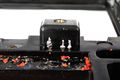
- 과열 방지 퓨즈
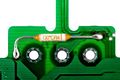
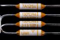
7A125V, 130'CR4, 213, UMI
- 중앙에 NTC 10k 오옴 온도센서
접지 연결을 위한 핀인듯
상단부위를 경사지게 갈아내어 저항값을 높이는 트리밍을 ㅤㅎㅒㅆ다.
- 대각선 측면에 NTC 10k 오옴 온도센서 두 개
- 외부에서 연결할 수 있는 피드 쓰루(feed-through) 3단자
기밀성 유지
- 히터 - natural graphite sheet 로 추정
6개 나사만 녹스는 철재(잘못 선택)
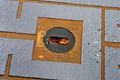
- 샘플 홀더
고무 가스켓
중앙에 NTC-10k 온도센서를 꼽기 위한 자리
- 위쪽이 샘플 홀더, 아랫쪽은 방열판
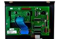
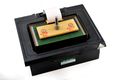
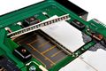
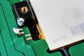
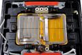
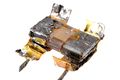
- 전원 및 제어보드
- 히트 싱크를 제거한 후 전체 사진
- AC입력단에 직렬로 사용된 NTC
- 외형
로고를 보면, Ametherm회사(종래? Ketema, Rodan Division), , RTI, SURGE-GARD, SG40, NTC, 10ohm@25'C 8A
고장나 있음.
- 팽윤제 12시간 + 코팅 뜯어내고 + 질산에 2분 + 알루미나 연마제
약 13오옴으로 측정됨.
- 외형
- 전원단에 상시 방전용 1k오옴 저항이 뜨거워져 PCB 쪽으로 단열 방법
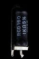
RCD160 1kohm 5%, all-welded wirewound construction
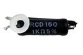
RCD Components Inc, 5W, 275'C까지, Hi-temp silicone coating
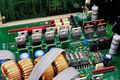
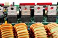
- 인덕터 - 모두 7개
- 외형
- 코어 구조
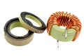
toroid core 두 개를 붙였다. 이름 모르겠다. 왜 두 개를 붙였는지 모르겠다.
- 코어를 깨보면
두 재료가 다르다.
- 외형
- 전해C
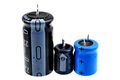
전극방향 표시(+를 표시할수도 있다.)
검정색잉크를 열로 눌러 , 105도씨, Vishay Sprague 678D-series
85도씨
-40도~+85도씨
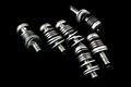
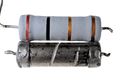
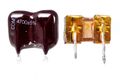
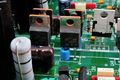
- 전류 제한용 저저항
- 6개 있음. Dale, LVR-3, 0.020오옴 1% 편차, Metal strip 저항체 구조
불에 빨갛게 태워도 불이 붙지 않는 수지.(유리섬유 함량이 매우 높은 듯)
블레이드 절삭 뒷면
블레이드 절삭 앞면
절삭면이 상당히 많이 테이퍼져 있음.
- 2개 있음
1오옴, 금색 5%
불에 빨갛게 태운 절연피막(전혀 타지 않음)을 벗기고.
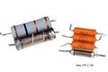
3W 제품과 크기 비교
나선 컷 확대
- 6개 있음. Dale, LVR-3, 0.020오옴 1% 편차, Metal strip 저항체 구조
- 운모C, CDM(Cornell Dubilier Electronics;CDE)
- 외형
4700pF, 5%, 1000V
열풍을 가해서 코팅 에폭시를 뜯어냄(내부는 타거나 녹지 않음)
- 분해
(튼튼한)리드 고정 방법, 내부 구조
운모판 중심에 전극을 형성하고, 좌우 교대로 금속 포일을 1/3 끼워넣어 접촉함.
- 외형
- 방열판 클립
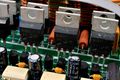
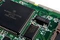
- FET, 레귤레이터, 정류기 등
- FET
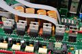
BUZ11 FET 5개, 7815 레귤레이터
BUZ11
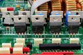
BUZ11, N-Channel Power MOSFET 50V, 30A, 40mohm
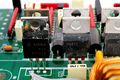
SAMSUNG KA7805, BUZ11
- 정류기
MBR1060, Schottky Barrier Rectifier, 10A 60V
MUR820 Ultrafast Recovery Time Rectifier, 200V 8A
MUG820G
- FET on/off control cicuit module(Gate Drive Circuit)
- FET
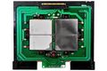
- CPU 보드
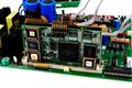
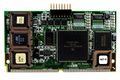
MC68HC11K, M68HC11 CPU core, 8-bit // TI LM12458CIV 12bit ADC
HM6264BLP-8L, 85ns, 28-pin plastic DIP, 64k SRAM (8-kword 8-bit) 1.5um
AT27C512R one-time programmable(OTP) ROM 512kb(64kB), AT28HC256 parallel electrically erasable and programmable(EEP) ROM 256kb(32kB), M29F040B 4Mb(512kB) non-volatile memory
PALCE 22V10H, simple programmable logic device(SPLD), 10 macrocells programmable logic
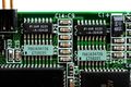
BI Technologies, 668-A-3241B, Resistor Network, 3241(324x10) B(0.1%) // CTS 766163472G 766-series 16:pin 3:isolated 472:4.7k G:+-2%
Fox Electronics FPX16.0, 12.9x5.0 H5.0, plastic encased SMD crystal
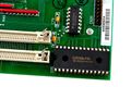
- 통신보드
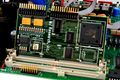
GPIB(NAT4882D) 및 RS232 보드
- 히트 싱크를 제거한 후 전체 사진


