"팅클발전소 솔라인버터, AC인버터"의 두 판 사이의 차이
잔글 (Togotech님이 팅클발전소 솔라인버터 문서를 팅클발전소 솔라인버터, AC인버터 문서로 이동했습니다) |
잔글 |
||
| 1번째 줄: | 1번째 줄: | ||
| − | 팅클발전소 솔라인버터 | + | 팅클발전소 솔라인버터, AC인버터 |
<ol> | <ol> | ||
<li> [[전자부품]] | <li> [[전자부품]] | ||
| − | |||
| − | |||
<ol> | <ol> | ||
<li> [[AC인버터]] | <li> [[AC인버터]] | ||
<ol> | <ol> | ||
| − | <li> [[팅클발전소 솔라인버터]] | + | <li> [[팅클발전소 솔라인버터, AC인버터]] - 이 페이지 |
| − | |||
</ol> | </ol> | ||
</ol> | </ol> | ||
| − | <li>팅클발전소 | + | <li>팅클발전소 제조 |
<ol> | <ol> | ||
<li>데이터시트 Twinkle Power Inverter, NPM-700x, NPM-1200x, NPM-1400x, NPM-1800x, NPM-2000x, NPM-2500x, NPM-4000x, NPM-5000x, NPM-6000x, NPM-7000x, NPM-8000x | <li>데이터시트 Twinkle Power Inverter, NPM-700x, NPM-1200x, NPM-1400x, NPM-1800x, NPM-2000x, NPM-2500x, NPM-4000x, NPM-5000x, NPM-6000x, NPM-7000x, NPM-8000x | ||
| + | <ol> | ||
| + | <li>스캔 | ||
<gallery> | <gallery> | ||
image:power_inverter05_001.jpg | image:power_inverter05_001.jpg | ||
image:power_inverter05_002.jpg | modified sine wave with PWM, pulse width modulation correction | image:power_inverter05_002.jpg | modified sine wave with PWM, pulse width modulation correction | ||
</gallery> | </gallery> | ||
| − | <li>12V(?) 30A | + | <li>입력으로 DC12V 또는 24V를 연결한다. |
| + | </ol> | ||
| + | </ol> | ||
| + | <li>위 데이터 시트에 나와있지 않는 어떤 모델을 분석함. | ||
| + | <ol> | ||
| + | <li>두 대를 분해해서 사진 촬영을 하였다. | ||
| + | <li>12V(?) 30A 입력에 사용되는 [[큰 바인딩 포스트]] | ||
<gallery> | <gallery> | ||
image:power_inverter04_001.jpg | image:power_inverter04_001.jpg | ||
| − | |||
image:power_inverter04_003.jpg | 입력 DC 단자 | image:power_inverter04_003.jpg | 입력 DC 단자 | ||
image:power_inverter04_004.jpg | 끝까지 다 조여도 닿지 않는다. 와셔를 반드시 사용해야 한다. | image:power_inverter04_004.jpg | 끝까지 다 조여도 닿지 않는다. 와셔를 반드시 사용해야 한다. | ||
| + | image:power_inverter04_004_001.jpg | 노출된 나사산 길이를 조정할 수 있다. | ||
| + | </gallery> | ||
| + | <li>출력패널. SOLAR INVERTER라고 적혀 있다. | ||
| + | <gallery> | ||
| + | image:power_inverter04_002.jpg | 출력 AC 단자 | ||
</gallery> | </gallery> | ||
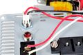
<li>내부 | <li>내부 | ||
<gallery> | <gallery> | ||
image:power_inverter04_005.jpg | image:power_inverter04_005.jpg | ||
| − | image:power_inverter04_007.jpg | | + | image:power_inverter04_007.jpg | PCB tinning을 적용한 [[고전류 동박]]이 아니다. PCB는 실리콘 [[실란트]]로 발라 고정했다. |
| + | </gallery> | ||
| + | <li>주변 부품에서 | ||
| + | <ol> | ||
| + | <li>AC 출력 단자에 [[AC전원용 CMF]]를 임시로 설치했다. 현재 회로에서는 EMI 승인에서 불합격이 되어 추가한듯 | ||
| + | <gallery> | ||
| + | image:power_inverter04_010.jpg | 왼쪽이 [[AC전원용 CMF]], 오른쪽은 [[토로이달L]] | ||
| + | image:power_inverter04_012.jpg | ||
| + | image:power_inverter04_012_001.jpg | EMI 제거용 1nF 1kV [[고압 단판 커패시터]] | ||
| + | </gallery> | ||
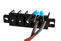
| + | <li> [[플레이드 퓨즈]] | ||
| + | <gallery> | ||
| + | image:power_inverter04_006.jpg | [[플레이드 퓨즈]] 10A 3개를 병렬로 사용하면서 [[대전류 검출용R]] 역할을 하는 듯. | ||
| + | image:power_inverter04_006_001.jpg | ||
| + | image:power_inverter04_006_002.jpg | ||
</gallery> | </gallery> | ||
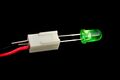
| − | <li> | + | <li> [[리드 LED 고정 방법]] |
<gallery> | <gallery> | ||
| − | image: | + | image:power_inverter04_011.jpg | 맞지 않는 클림프 터미날로 리드 LED를 연결하는 방법. 풀칠을 추가했다. |
| − | + | image:power_inverter04_011_001.jpg | |
| − | image: | ||
| − | |||
| − | |||
</gallery> | </gallery> | ||
| + | </ol> | ||
| + | <li>회로보드에서 | ||
| + | <ol> | ||
| + | <li>IC | ||
| + | <gallery> | ||
| + | image:power_inverter04_008.jpg | PIC16F716 두 개 사용, MC33152: dual[[MOSFET]] Driver, IR2109S [[MOSFET]] and IGBT drivers, PC-17K1 AUK Photocoupler | ||
| + | </gallery> | ||
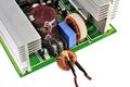
| + | <li>전력용 디스크리트 | ||
| + | <gallery> | ||
| + | image:power_inverter04_013.jpg | 트랜스와 연결된 IRFB4410 [[MOSFET]] 100V 10mΩ@10V 88A 4개, AC 출력 PWM용 FDPF18N50 [[MOSFET]] 500V 265mΩ@9V 18A 4개 | ||
| + | image:power_inverter04_014.jpg | MUR860 8A 600V Ultrafast [[정류다이오드]] | ||
| + | </gallery> | ||
| + | <li>회로 수정 | ||
| + | <gallery> | ||
| + | image:power_inverter04_015.jpg | [[마킹없는 IC]], 마킹을 지운 IC와 좌우에 있는 [[TO-220]] 두 부품을 보니 | ||
| + | image:power_inverter04_016.jpg | [[리니어 레귤레이터]] KA7815, 뜨거워져 PCB를 수정하지 않고 방열판을 추가한 후 구부려 장착했다. | ||
| + | image:power_inverter04_017.jpg | IRF3205 [[MOSFET]] 55V 8mΩ@10V 110A, 설계 오류를 해결하기 위해 gate 핀에 100Ω저항을 추가했다. | ||
| + | </gallery> | ||
| + | <li>기타 | ||
| + | <gallery> | ||
| + | image:power_inverter04_009.jpg | [[SMPS용 트랜스포머]]에 풀로 붙인 [[NTC 온도센서]] | ||
| + | image:power_inverter04_010.jpg | AC 출력에 있는 [[토로이달L]]은 풀칠하지 않아 흔들림. | ||
| + | </gallery> | ||
| + | </ol> | ||
</ol> | </ol> | ||
</ol> | </ol> | ||
2025년 4월 1일 (화) 21:23 기준 최신판
팅클발전소 솔라인버터, AC인버터
- 전자부품
- AC인버터
- 팅클발전소 솔라인버터, AC인버터 - 이 페이지
- AC인버터
- 팅클발전소 제조
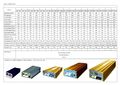
- 데이터시트 Twinkle Power Inverter, NPM-700x, NPM-1200x, NPM-1400x, NPM-1800x, NPM-2000x, NPM-2500x, NPM-4000x, NPM-5000x, NPM-6000x, NPM-7000x, NPM-8000x
- 스캔
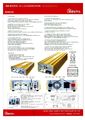
modified sine wave with PWM, pulse width modulation correction
- 입력으로 DC12V 또는 24V를 연결한다.
- 스캔
- 데이터시트 Twinkle Power Inverter, NPM-700x, NPM-1200x, NPM-1400x, NPM-1800x, NPM-2000x, NPM-2500x, NPM-4000x, NPM-5000x, NPM-6000x, NPM-7000x, NPM-8000x
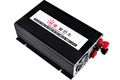
- 위 데이터 시트에 나와있지 않는 어떤 모델을 분석함.
- 두 대를 분해해서 사진 촬영을 하였다.
- 12V(?) 30A 입력에 사용되는 큰 바인딩 포스트
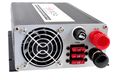
입력 DC 단자
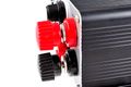
끝까지 다 조여도 닿지 않는다. 와셔를 반드시 사용해야 한다.
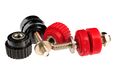
노출된 나사산 길이를 조정할 수 있다.
- 출력패널. SOLAR INVERTER라고 적혀 있다.
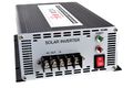
출력 AC 단자
- 내부
- 주변 부품에서
- AC 출력 단자에 AC전원용 CMF를 임시로 설치했다. 현재 회로에서는 EMI 승인에서 불합격이 되어 추가한듯
EMI 제거용 1nF 1kV 고압 단판 커패시터
- 플레이드 퓨즈
- 리드 LED 고정 방법
맞지 않는 클림프 터미날로 리드 LED를 연결하는 방법. 풀칠을 추가했다.
- AC 출력 단자에 AC전원용 CMF를 임시로 설치했다. 현재 회로에서는 EMI 승인에서 불합격이 되어 추가한듯
- 회로보드에서


